Mayline Dual Adjustment Drafting Table User Manual
Assembly instructions
ASSEMBLY INSTRUCTIONS
COMPONENTS:
A. Stand Sub-Assembly.........1
B. Table Feet w/ Glides..........2
FRONT
NOTE: Assembly is best performed by 2 people.
1. Remove the stand components from the shipping carton
and inspect for shipping damage. Reject if any damage is
evident.
2. Check the parts list to assure that the parts received are
the same as the parts required to assemble the unit. Also
assure the quantities are correct.
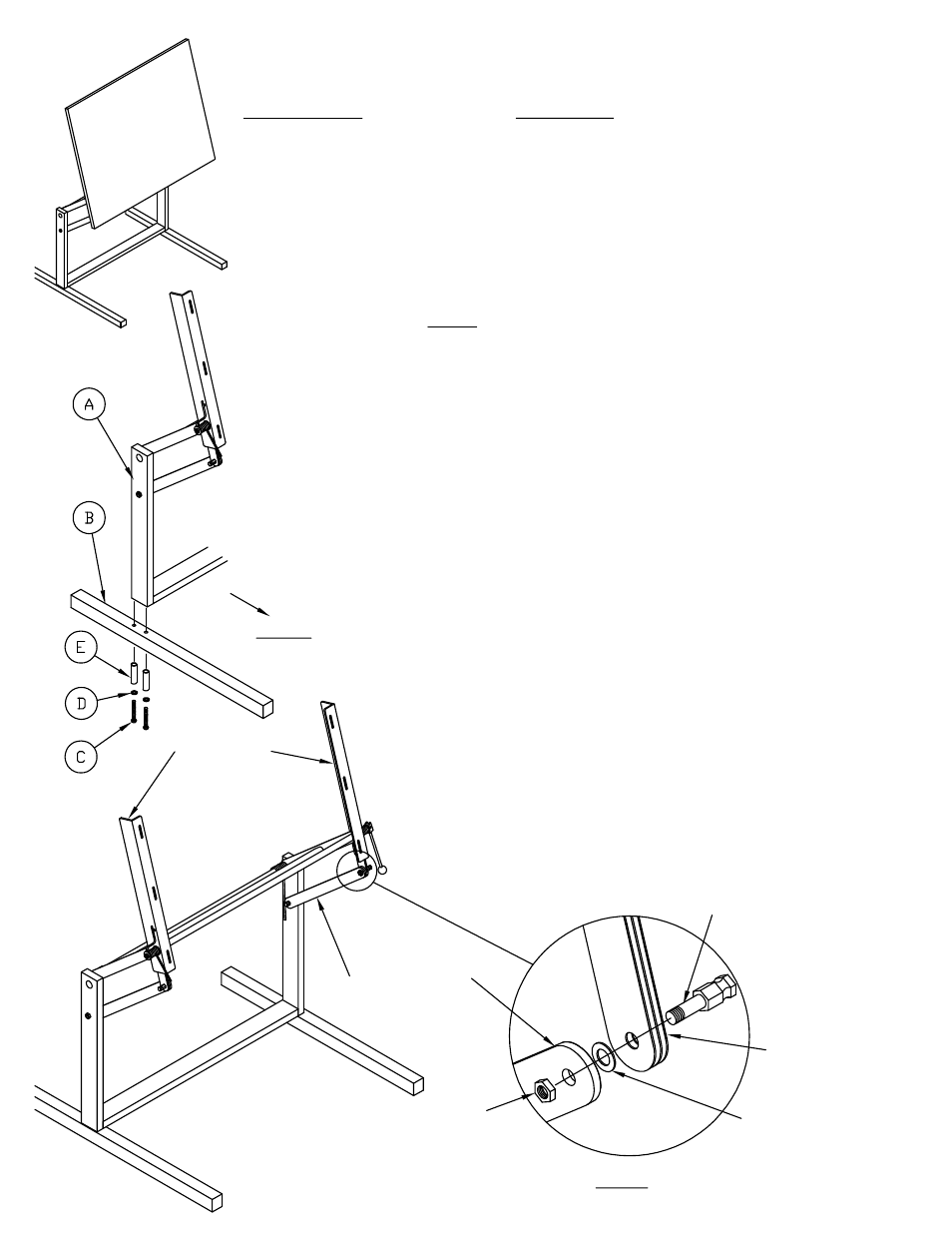
3. Assemble the Table Feet (B) to the bottom of the Stand
Sub-Assembly (A) with two Screws (C), two Sleeves (E), and
two Large Washers (D) per Foot. Position the longer portion
of the foot toward the front. Tighten these screws with
Combination Wrench (H) provided.
4. Swing the table mount to a vertical position and carefully
release Brake Lever. Temporarily remove the nut from the
bolt holding the Brake Leaves. Swing Tilt Support Arm up
and slide arm onto end of brake leaf bolt. Tighten Hex nut to
secure Arm and Leaves. Repeat this step for both Tilt
Support Arms.
Table Mount
Tilt Support Arm
Hex Nut
(inside)
Washer (between Arm
and Brake Leaves)
Brake Leaves
HARDWARE:
C. M8 x 80mm Socket Head Cap Screw...............4
D. Large Washer....................................................4
E. Sleeve................................................................4
F. Tension Cube.....................................................2
G. M8 x 16 Hex Head Screw..................................2
H. 13 mm x 17 mm Combination Wrench...............1
J. Spring Spanner Tube..........................................1
Brake Leaf Bolt
Fig. 1
(1)