System start-up, Vii. system start-up – Burnham 20_PV_I User Manual
Page 13
13
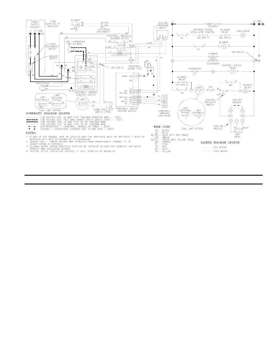
Figure 10: Wiring Diagram
Figure 11: Main Burner Installation
VII. System Start-up
A.
Safe operation and other performance criteria were
met with gas manifold and control assembly provided
on boiler when boiler underwent tests specified in
American National Standard for Gas-Fired Low-
Pressure Steam and Hot Water Boilers, ANSI Z21.13.
B.
Fill heating system with water and vent air from
system. Use the following procedure on a Series Loop
System equipped with zone valves. See Figure 3.
1. Close isolation valve in boiler supply piping.
2. Isolate all circuits by closing zone valves or
balancing valves.
3. Attach hose to bib cock located just below isolation
valve in boiler supply piping. Terminate hose in
five gallon bucket at a suitable floor drain or
outdoor area).
4. Starting with one circuit, open zone valve.
5. Open bib cock.
6. Open fill valve. Makeup water line should be
located directly above isolation valve in boiler
supply piping.
7. Allow water to overflow from bucket until
discharge from hose is bubble free for 30 seconds.
8. Open zone valve to second zone to be purged, then
close first. Repeat this step until all zones have been
purged, but always have one zone open. At
completion, open all zone valves.
9. Close bib cock, continue filling system until
pressure gauge reads 12 psi. Close fill valve.
Note: If makeup water line is equipped with
pressure reducing valve, system will automatically
fill to 12 psi. Leave globe valve open.
10.Open isolation valve in boiler supply piping.
11.Remove hose from bib cock.
C.
Check main burners. See Figure 11. Rear of burner
must be in vertical slot in rear of burner tray. Front of
burner must be seated on orifice.