Longevity MIGWELD 140 User Manual
Page 19
MigWeld 140 140 AMP MIG Welder
Page 19 of 27
10
9
8
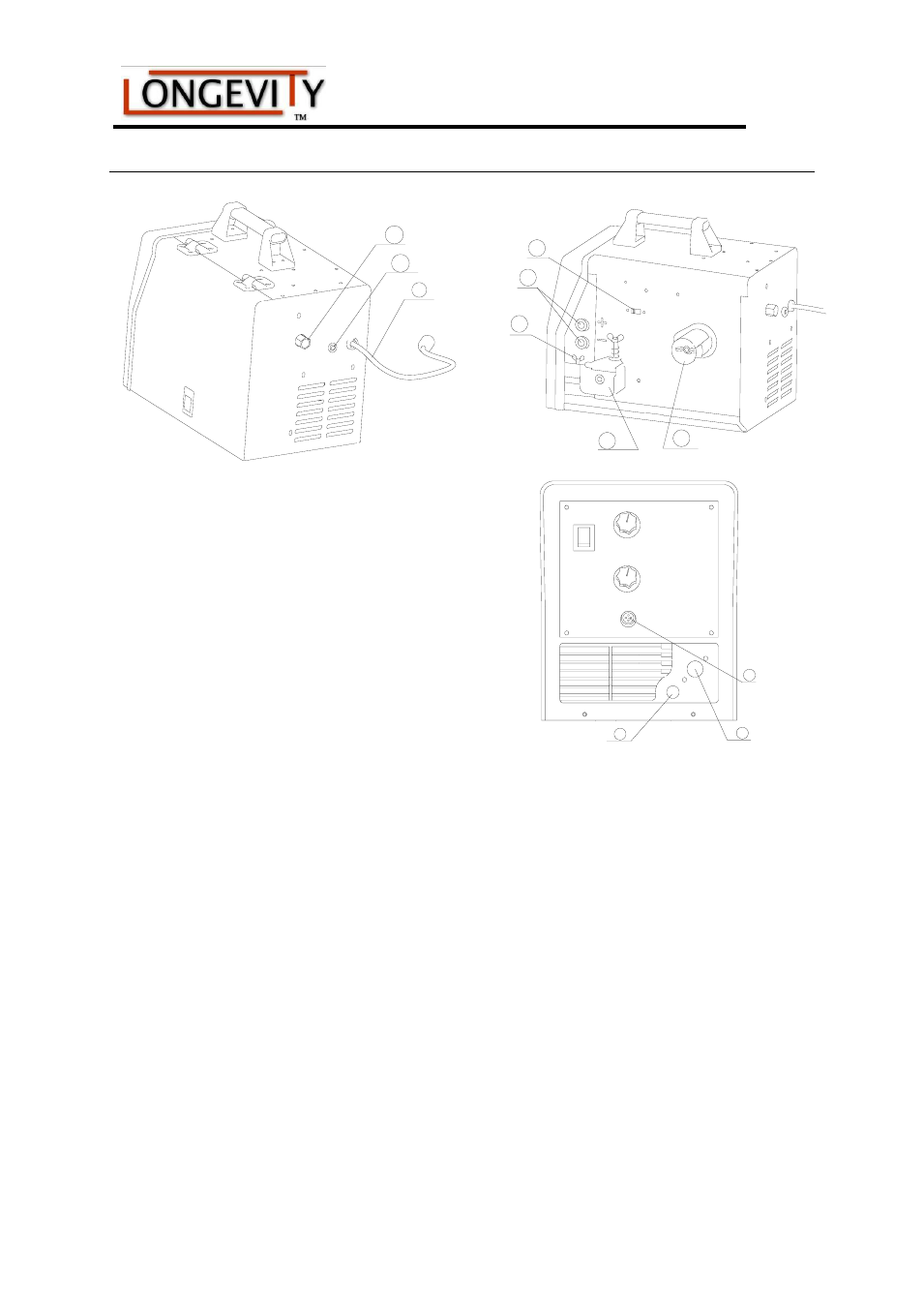
III. INSTALLATION
Grounding (work) Clamp Installation
(See Figure C-1, Figure C-2)
1. Open the right-side door of the welding
machine
2. Insert the lug end of the ground clamp
through access hole○
2
3. Route the cable of the ground clamp
around the wire feed gearbox and
connect it to the negative (-) output
terminal of the welding machine
4. Tighten the lug plate attached to the
end of the wire with wing screw④. Figure C-1
NOTE: This above method of connection is GMAW. When gasless flux-cored wires are used,
connect the cable of the ground clamp to the positive (+) output terminal of the welding
machine. The short power cable must be removed from this lug and placed on the negative (-)
terminal. (See Reference Table T-1)
Welding Gun Installation (See Figure C-1, C-2 and C-3)
There is one spool of .025” (0.6mm) solid welding wire included with the welder. The
welding gun comes with a .025” (0.6mm) contact tip ○
6
installed. If .030-.035” (0.8-0.9mm)
wire is to be used, change the contact tip to the appropriate size.
Connect the welding gun to the welding machine.
1. Power off the welding machine (switch is positioned at “O”).
2. Plug the welding gun into the access hole ○
1
and plug it into to the connector block.
Also, thread the control wire of the welding gun through the access hole○
1
and inset the
control wire into the gun trigger connector terminals. ○
5
15
12
11
13
14
5
2
1