Figure 1, Ab c – Lightforce DRIVING LIGHT WIRING HARNESS User Manual
Page 2
LIGHTFORCE AUSTRALIA PTY LTD • 28 Orsmond Street, Hindmarsh SA 5007 Australia • www.lightforce.com | email: [email protected]
Australia: Tel: 08 8440 0888 | Fax: 08 8346 0504 • Int’l: Tel: +618 8440 0888 | Fax: +618 8346 0504
All logos and images are subject to relevant trademark and copyright protection LIGHTFORCE Pty Ltd | © October 2012 • Data and specifications contained maybe subject to change without notice.
LIGHTFORCE Australia Pty Ltd shall not be liable for damage, malfunction, failure resulting from accident, misuse, misapplication, unauthorised repair, neglect, modification, unauthorised or non standard replacement parts,
accessories, bulbs, batteries or voltage or operation of the product beyond its technical and or environmental specification.
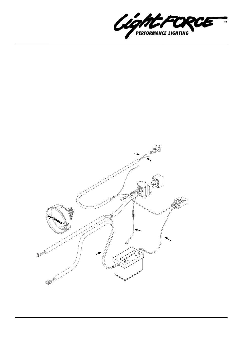
Figure 1
If the lights do not operate correctly check the following:
• Recheck all installation steps.
• Inspect fuse holder for blown fuse.
• Inspect all ground wires for good earth.
• Check switch operation.
• Check Tee Tap connection
NOTE 1: Some automotive manufacturers use the negative circuit to activate the high beam. In this situation, unplug A (yellow/
black wire with the open ring) from B. B is not used and remains disconnected. Plug C (female) into B (male). Cable A is
now not required, discard. In this configuration the LED indicator on the switch will not operate.
NOTE 2: This wiring harness is designed for the use of two lights only - not exceeding 9amps per light. Should extra light(s) be
fitted additional wiring harness is required.
Black
Black/Yellow
A
B
C
Yellow
Black/Red
Brown
D
Connect to the high beam circuit (figure 3)