5 resistor configurations, 4 exploded view, 2 procedure – Lenze MC Series dynamic braking and form C relay User Manual
Page 2: 3 wiring and programming
Lenze Americas • 630 Douglas Street • Uxbridge, MA 01569 • USA
Sales: (800) 217-9100 • Service: (508) 278-9100 • www.lenzeamericas.com
Lenze Americas • 630 Douglas Street • Uxbridge, MA 01569 • USA
Sales: (800) 217-9100 • Service: (508) 278-9100 • www.lenzeamericas.com
MDB01B
13360127
MDB01B
13360127
1.5 RESISTOR CONFIGURATIONS
When the Dynamic Braking Kit is ordered separately from the MC Series drive, the resistor assembly will be shipped in the 480 Vac and 590 Vac
configuration. For 240 Vac units, the resistor configuration must be modified, as shown below, using the hardware included with the kit.
Note
If the Dynamic Braking option is ordered with the drive, the resistor assembly will be shipped in the proper configuration, and no
modification is required
SCREW (TYPICAL 4 PLCS.)
SHOULDER WASHER
(TYPICAL 4 PLCS.)
1 5/16" STANDOFF
(TYPICAL 3 PLCS.)
2 X 6 PIN CONNECTOR
3/4" STANDOFF
SHOULDER WASHER
7/16" STANDOFF
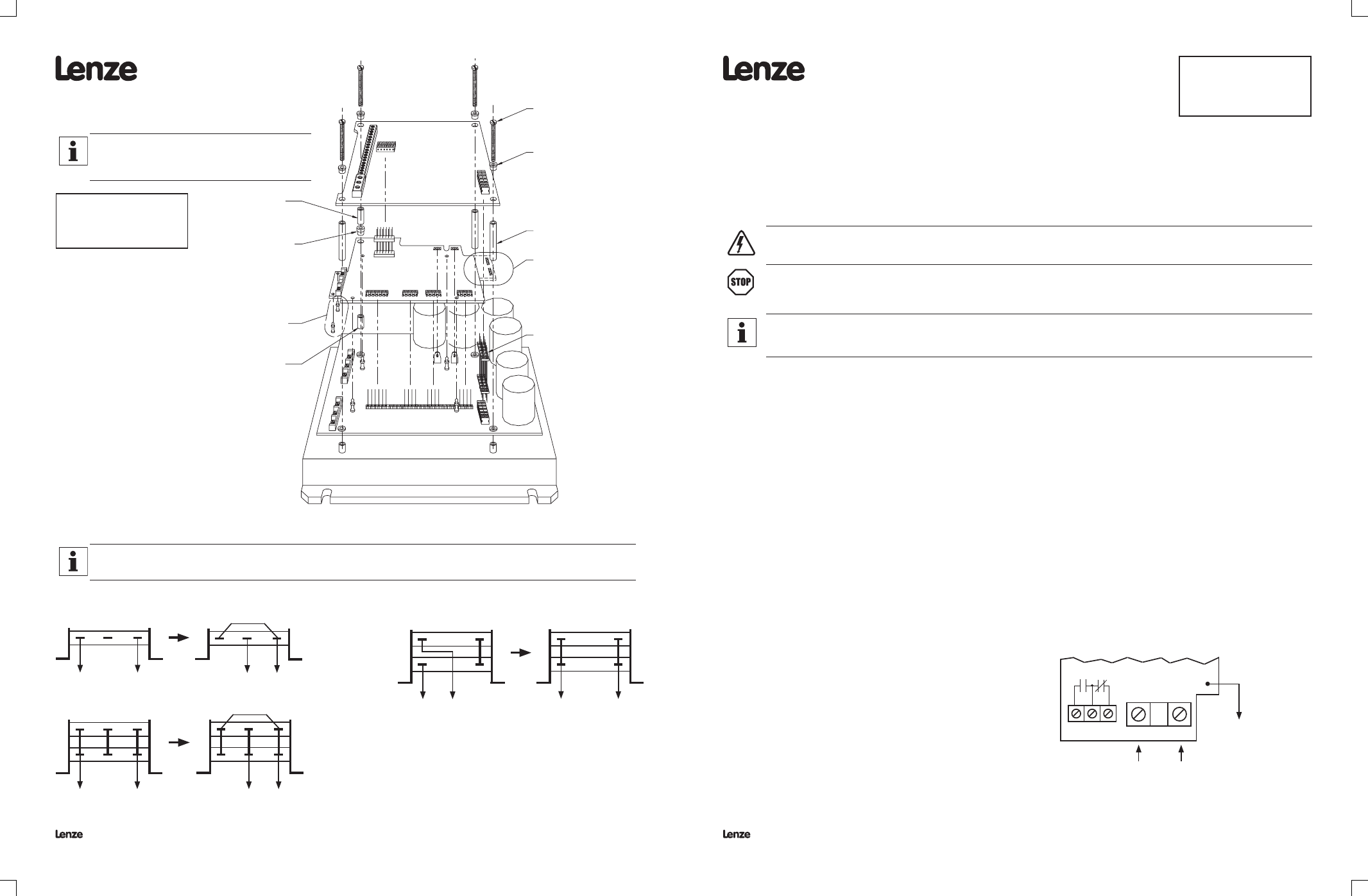
1.4 EXPLODED VIEW
Applies to kits:
842-001, 842-002, 842-005
843-001, 843-006
Note
Dynamic Braking Board is shown for illustration
purposes. The Additional Form C Relay Board is very
similar and the installation procedure is the same.
Add jumper between Tab #1 and Tab #3, and move the RED wire to Tab #2.
RED
BLUE
480 Vac & 590 Vac
RED
BLUE
RED
BLUE
480 Vac
240 Vac
841-007
1
2
3
RED
BLUE
Jumper
Jumper
RED
BLUE
RED
BLUE
1
2
3
240 Vac
841-002, 841-003
841-004, 841-005, 841-006
STANDOFFS ONLY
PRESENT IN 7.5 HP KIT
(9956-XXX DB BOARD)
LOCATION OF P8 & P9 ON
7.5 HP DB BOARD (9956-XXX)
1
2
3
1
2
3
1
2
3
1
2
3
Connect each Tab #1 together with screw provided (copy the
configuration of the #2 tabs), and move the BLUE wire to Tab #2.
1
2
1
2
1
2
1
2
}
}
}
}
}
}
}
}
}
}
}
}
P2
P3
P9
P8
A
B
C
D
PL2
HEATSINK
POWER BOARD
BRAKING BOARD
MAIN CONTROL BOARD
PL1
P3
0.5 - 5 HP @ 240 Vac
1 - 7.5 HP @ 480 Vac
1 - 5 HP @ 590 Vac
7.5 - 30 HP @ 240 Vac
10 - 60 HP @ 480 Vac
7.5 - 60 HP @ 590 Vac
2.0 INSTRUCTIONS FOR KITS: DYNAMIC BRAKING:
842-006, 842-007
ADDITIONAL RELAY:
843-007, 843-008
1.1 PARTS LIST
(1) Dynamic Braking Board (9955-XXX)
(1) Resistor assembly (if ordered)
(2) Screw with captive lock washer
(2) Metal "male-female" standoff
(2) Large flat washe
((2) Small flat washer
(2) Lockwasher
(2) Nylon “snap-in” standoff
2.2 PROCEDURE
DANGER!
Hazard of electrical shock! Remove power from the drive and wait three minutes before attempting this procedure.
DC Bus capacitors retain charge after power is removed..
STOP!
The internal components of the MC Series drive can be damaged by electrostatic discharge (ESD)! Use an antistatic wrist strap with
the ground clip attached to the drive ground lug when attempting this procedure. Always place components on antistatic surfaces or in
antistatic bags when they are not being handled during this procedure.
Note
Refer to 2.4 Exploded View while performing this procedure. This view is from the right side of the drive.
Be careful when removing and installing boards, as there are many pins that can be easily bent.
1.
With the drive cover removed, remove the keypad assembly. On NEMA 1 units, this is done by prying one end of the bracket up and out. On NEMA 4 or 12 units,
remove the screws that hold the bracket in place. Then unplug the keypad ribbon cable from the Main Control Board (9933A-XXX or 9019-XXX).
2.
Remove the Main Control Board by unscrewing the four screws (one at each corner) and lifting the Main Control Board straight up and out.
There is a 2 x 6 pin connector that connects the P3 plug on the Main Control Board to the P3 plug on the Power Board below. Leave this plugged into the P3 plug on
the Power Board.
3.
Under the Main Control Board is the Driver Board (9941-XXX) which must be removed to install the DB & Relay Board. Remove the Driver Board by pinching the
flared top of each nylon standoff while gently lifting up on the board (leave the standoffs snapped into the Power Board underneath).
Remove and save the 2 x 6 pin connector (see 2.4 Exploded View) that is plugged into PL2 on the Driver Board (another 2 x 6 pin connector may be included in the
DB & Relay kit; only one is needed).
Once the Driver Board is removed, examine the Power Board. There will be three screws in a row between the Bus Capacitors and the PL1 connector. Some units will also
have two standoffs labeled "P" and "B" located below the row of screws. If the Power Board has the "P" and "B" standoffs, go to Step 6. If not, continue with Step 4.
4.
There are three screws in a horizontal row located between the Bus Caps and the PL1 connector on the Power board. Remove and discard the middle and right
screws (which are the middle and bottom screws as viewed in 2.4 Exploded View).
5.
Install the two metal “male-female” standoffs where the screws were removed in Step 5, using the large flat washers and lockwashers.
6.
Install the two nylon “snap-in” standoffs into the holes near the DB1 and DB2 terminals.
7.
Snap the DB & Relay Board into place where the old Driver Board was, onto the same nylon standoffs that held the Driver Board in place.
Make sure that the PL1 and PL3 pin connectors make positive contact through the bottom of the DB & Relay Board.
8.
Install the two screws with captive lockwashers at the top of the DB & Relay Board at the positions marked "P" and "B", using the small flat washers.
9.
Install the 2 x 6 pin connector in PL2 on the DB & Relay Board.
10. Re-install the Main Control Board. Make sure that the PL2 and P3 pin connectors make positive contact through the bottom of the Main Control Board.
11. Re-install the keypad assembly and drive cover.
2.3 WIRING AND PROGRAMMING
Refer to the diagram to the right for wiring.
To enable Dynamic Braking, set DYN BRAKE (parameter 14) to ON.
To enable the Additional Form C Relay, set TB-14 OUT (parameter 52) to the
desired status indication.
Refer to the drive's Installation and Operation Manual for more info on
programming.
YELLOW WIRE
To TB-14 on Main
Control Board
RED
WIRE
BLUE
WIRE
From Resistor Assembly
DB & Form C
Relay Board
DB1
DB2
19 20 21