Lenze RS-485 module User Manual
Page 10
8
ENGLISH
Parameter Setting
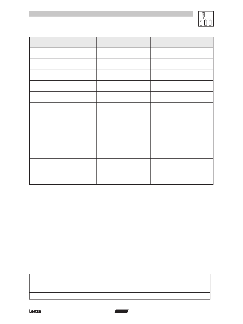
ModBus Register
16 bit address
Type
Controller Variable
Description
68
16 bit word
InBounceDelay for input 2
See Drive 94 manual
W: EPROM & memory.
69
16 bit word
OutFunc for output 1
See Drive 94 manual
W: EPROM & memory.
70
16 bit word
OutFunc for output 2
See Drive 94 manual
W: EPROM & memory.
71
16 bit word
OutPolarity for
output 1
See Drive 94 manual
W: EPROM & memory.
72
16 bit word
OutPolarity for
output 2
See Drive 94 manual
W: EPROM & memory.
73
16 bit word
ControlWord
2 – Quick Stop
3 – Enable Drive
4 – Disable Drive
5 – Fault Reset
6 - Continue
W: Memory only
75
32 bit dword
TargetVelocity
This register could provide the
Target Velocity when the drive is
in normal velocity mode.
W: Memory only.
Low word starts first
77
16 bit word
TargetTorque
This register could provide the
Target Torque when the drive is
in normal velocity mode.
W: Memory only.
Low word starts first
4.2
Discrete Memory
4.2.1 Discrete Inputs (Read Only Bits)
The following read only ModBus bit registers (drive bit variables) accessible only through the ModBus
function
•
02 (0x02) Read Discrete Inputs
4.2.2 Coils (Read/Write Bits)
The following read/write ModBus bit registers (drive bit variables) accessible only through the ModBus
functions
•
01 (0x01) Read Coils
•
05 (0x05) Write Single Coil
•
15 (0x0F) Write Multiple Coils
Modbus Register
16 bit address
Type
Description
1 (0x0001)
BIT
Digital OUT1
2 (0x0002)
BIT
Digital OUT2