Ss108, Switch or relay enable plc enable ttl logic enable – Lenze SQT01B User Manual
Page 2
PC COMPUTER
RS-232 INTERFACE
Motor
Feedback
BLDC
MOTOR
SS108
CONNECTOR DB15
CONNECTOR DB9
A-
Hall A-
B+
Hall A+
B-
Hall B+
Z+
Hall C+
Z-
Hall B-
Encoder COM
Hall C-
A+
+5VDC (Encoder Power)
10
2
9
DS1
15
7
14
6
13
5
12
4
11
3
1
TB2
SEE DETAIL A4
TB1
SEE DETAIL A3
TB1
8
A
N
A
L
O
G
/D
IG
IT
A
L
I/
O
TX
RX
DS2
5
9
4
8
3
7
2
6
1
RS-232
TB1
80 - 170 VDC
TO MOTOR
TO MOTOR
DC-
DC+
1
2
3
4
5
U (R)
V (S)
W (T)
U (R)
V (S)
W (T)
TB1
100 - 120 VAC
1
2
3
SS108
SS208
SS108DC
SS208DC
DC Series
AC Series
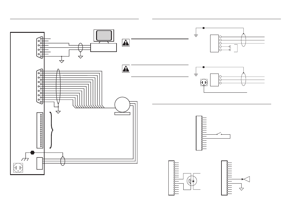
Detail A1 | Motor and Host computer connection
Detail A2 | Incoming power connection
Detail A3 | Enable Options
1
2
3
4
5
6
7
8
9
10
11
12
13
14
15
16
ENABLE
1
2
3
4
5
6
7
8
9
10
11
12
13
14
15
16
1
2
3
4
5
6
7
8
9
10
11
12
13
14
15
16
5V TTL/CMOS LOGIC
PLC OUTPUT
CONTROLLER
LOGIC
COMMON
Switch or Relay Enable
PLC Enable
TTL Logic Enable
Hazard of electrical shock! Circuit potentials are
at 115 VAC or 230 VAC above earth ground. Avoid
direct contact with the printed circuit board or with
circuit elements to prevent the risk of serious injury
or fatality. Disconnect incoming power and wait 60
seconds before servicing drive. Capacitors retain
charge after power is removed.
DO NOT connect incoming power to the output
motor terminals (U, V, W)! Severe damage to the
drive will result.