Detail a1 | simple torque and velocity system, Detail a2 | input power connections, Servo motor – Lenze SQF01C User Manual
Page 2
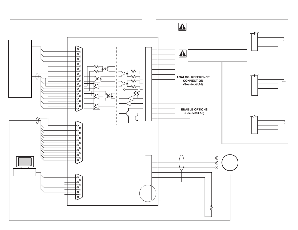
Detail A1 | Simple Torque and velocity system
MB+/DIR+
MA-/STEP-
MA+/STEP+
N/C
Encoder power
COM
Encoder Z-
Encoder Z+
Encoder B-
Encoder B+
Encoder A-
Encoder A+
ENABLE-
Ready Out-C
+5V 20ma
COM
REF+
REF-
MB-/DIR-
Ready Out-E
Aux Out-E
Aux Out-C
ACOM
ENABLE+
Shield
13
25
12
24
11
23
10
22
9
21
8
20
7
19
6
18
5
17
4
16
3
15
2
14
1
HALL B+
Encoder power
HALL C-
HALL A+
HALL A-
HALL B-
HALL C+
Encoder Z+
Shield
Encoder B-
Encoder B+
Encoder Z-
Encoder A+
COM
Encoder A-
DB15
TB504
8
15
7
14
6
13
5
12
4
11
3
10
2
9
1
COM
RS-232 TX
RS-232 RX
DB9
TB505
5
9
4
8
3
7
2
6
1
W
V
U
Servo
Motor
Hall Sensors
and Encoder
-10V
REF-
REF+
+10V
AGND
MA+/STEP+
MA-/STEP-
MB+/DIR+
MB-/DIR-
Analog Output
Aux Input
ENABLE
Ready Output
Aux Output
COM
TB502
15 Pin Terminal
1
2
3
4
5
6
7
8
9
10
11
12
13
14
15
Line Driver
+5V
26LS31
V(S)
U(R)
DUMP-
DUMP+
W(T)
GND
TB501
9 Pin Terminal
DB25
TB506
40 Ohm 100W
Dump Resistor
MOTION
CONTROLLER
1
2
3
4
5
6
INPUT POWER CONNECTION
(See detail A2)
PC COMPUTER
Detail A2 | Input power connections
TB501-8 Pin
SINGLE PHASE
AC SERIES
GND
L1
L2
6
7
8
THREE PHASE
AC SERIES
TB501-9 Pin
L1
GND
L2
L3
6
7
8
9
SSxxx-3P Systems Only
DC SERIES
TB501-8 Pin
GND
DC+
DC-
6
7
8
Hazard of electrical shock! Circuit potentials are
at 115 VAC or 230 VAC above earth ground. Avoid
direct contact with the printed circuit board or with
circuit elements to prevent the risk of serious injury
or fatality. Disconnect incoming power and wait 60
seconds before servicing drive. Capacitors retain
charge after power is removed.
DO NOT connect incoming power to the output
motor terminals (U, V, W)! Severe damage to the
drive will result.