Function library lenzecandsxdrv.lib, Functions/function blocks – Lenze DDS Global Drive PLC Developer Studio User Manual
Page 20
3.6
L_CanDSxHeartBeat − Execution of "Heartbeat"
Function library LenzeCanDSxDrv.lib
Functions/function blocks
3−8
L
LenzeCanDSxDrv.lib EN 1.2
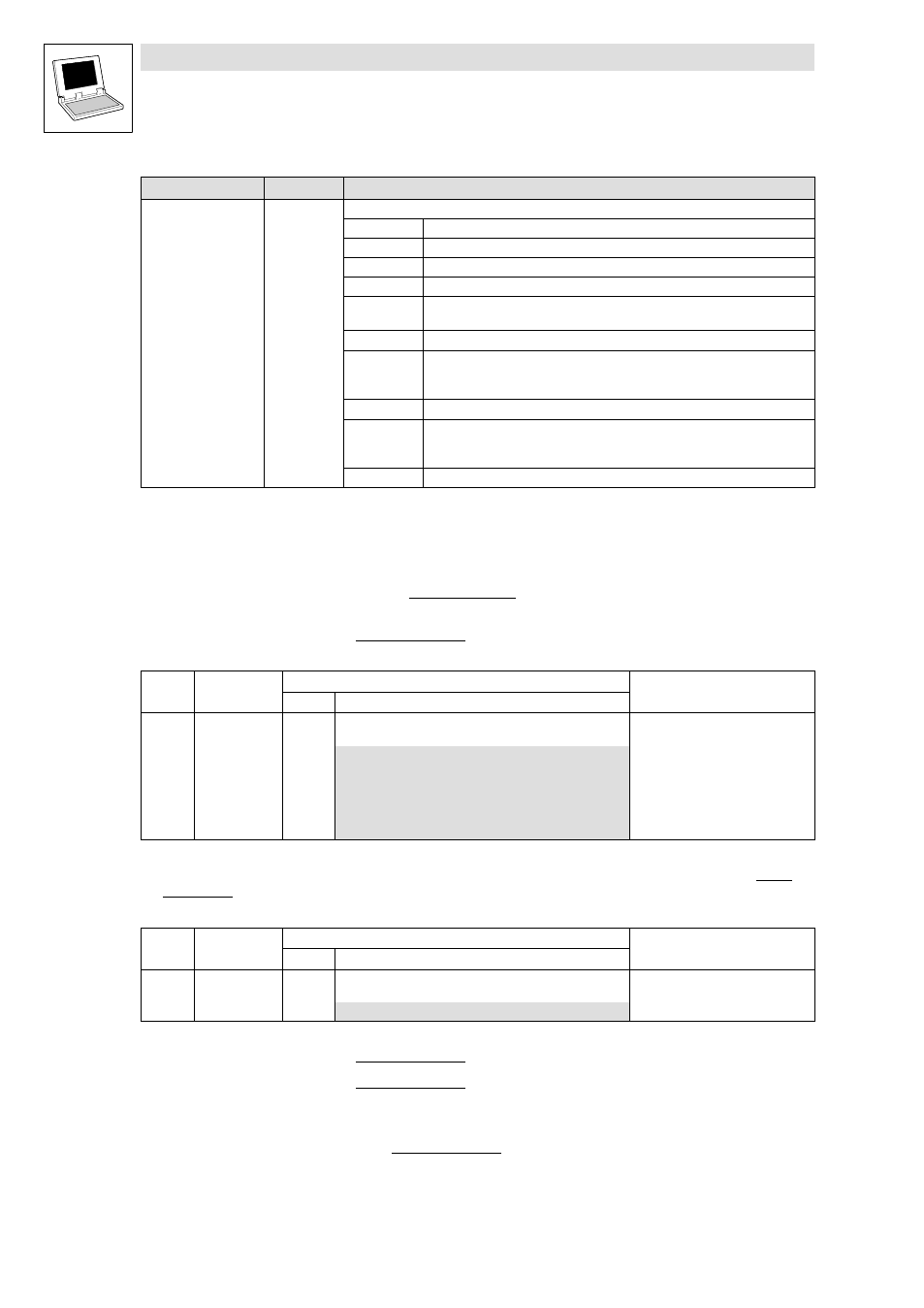
Outputs
Data type
Information/possible settings
nState
Integer
Status
300 FB is deactivated ( bRun = FALSE).
127 Bus device to be monitored is in CAN state Pre−operational.
5 Bus device to be monitored is in CAN state Operational.
4 Bus device to be monitored is in CAN state Stopped.
0 Bus device to be monitored is in CAN state Boot−up
or FB is not activated.
−5 Monitoring time tHeartBeatConsumerTime is set to "0".
−10 "Heartbeat" event:
The "Heartbeat" message from the bus device to be monitored was not received
within the selected monitoring timetHeartBeatConsumerTime.
−12 The selected node address ( byNodeAddr) is invalid.
−120 The monitoring mechanism has not been initialised in the CanDSx driver.
·
Use the function L_CanDSxOpenHeartBeat to initialise the monitoring
mechanism.
−121 The selected driver number ( wDrvNr) is invalid.
Settings required for the PLC to be monitored
(Valid for 9300 Servo PLC/Drive PLC as from V6.2)
Select the following settings for the PLCto be monitored to ensure that the PLC will act as "Heartbeat
producer":
1. Set code C0352 of the PLC to be monitored to "3" to configure the PLC as "slave and
Heartbeat producer":
Code
LCD
Possible settings
Info
Lenze
Selection
C0352 CAN mst
0
System bus:
Master/slave configuration of the PLC
0
Slave (boot−up not active)
1
Master (boot−up active)
2
Master with Node Guarding
(SyncReceived no longer possible)
3
Slave and Heartbeat producer
4
Slave with Node Guarding
2. Use C0381 to select the time interval for sending the "Heartbeat" message in the PLC to be
monitored. Depending on the bus load, it is recommended to select a setting between 200 ...
2000 ms:
Code
LCD
Possible settings
Info
Lenze
Selection
C0381 HeartProTime
0
System bus: Heartbeat (slave):
HeartbeatProducerTime
0 {1
msec}
65535
3. Set code C0003 of the PLC to be monitored to "1" to save the new settings fail−safe.
4. Set code C0358 of the PLC to be monitored to "1" to carry out a CAN Reset Node.
– As an alternative, the CAN Reset Node can also be carried out by means of a fresh
power−on.
After the CAN Reset Node, the PLC to be monitored ("Hearbeat" producer) will continuously send
the "Heartbeat" telegram within the time interval selected under C0381 via the system bus. The
"Heartbeat" monitoring can now be activated in the monitoring PLC.