Voltage supply, Electrical installation – Lenze E82ZAFLC001 User Manual
Page 47
Electrical installation
Voltage supply
EDK82ZAFLC−001 DE/EN/FR 5.0
47
l
H2_SpgVersorgg−INS_Klemm
Voltage supply
)
Note!
Always use a separate power supply unit in every control cabinet and safely
separate it according to EN 61800−5−1 ("SELV"/"PELV") in the case of external
voltage supply and larger distances between the control cabinets.
DC voltage supply
Internal
The internal voltage is provided at terminal X3.3/20. It serves to supply the
controller inhibit (CINH).
External
The external voltage supply of the function module is required if communication is
to be maintained during a failure of the standard device supply.
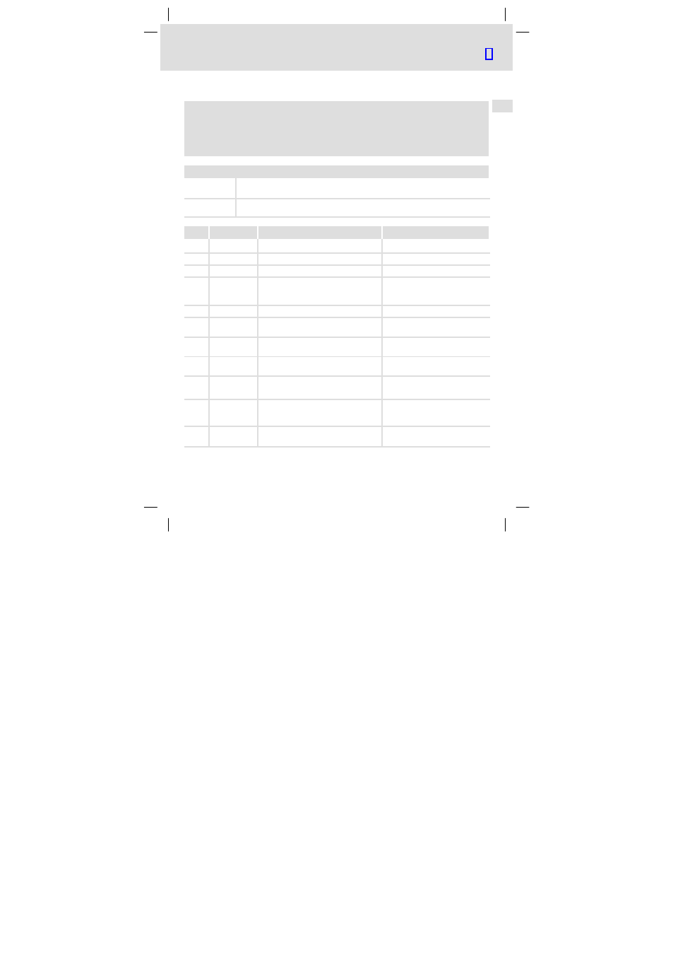
X3/
Designation
Function
Level
+
Additional HF−shield termination
A
T/R(A)
RS485 data line A
B
T/R(B)
RS485 data line B
CN
CNTR
*)
During data transmission:
CNTR = HIGH
+5 V (reference: GND3)
VP
*)
+5 V (reference: GND3)
40
GND3
Reference potential for LECOM−B
network *)
7
GND1
Reference potential for the internal
supply at X3/20
39
GND2
Reference potential of controller inhibit
(CINH) at X3/28
28
CINH
Controller inhibit
l
Start = HIGH (+12 ... +30 V)
l
Stop = LOW (0 ... +3 V)
20
DC voltage source for internal supply of
controller inhibit (CINH)
+20 V (reference: GND1)
59
External DC supply for the function
module
U(ext.) = +24 V DC
±
10%
(reference: GND1)
*) e.g. if a repeater is connected