Universal iso grips, Installation – Kuryakyn 6241 UNIVERSAL ISO GRIPS User Manual
Page 2
PAGE
2
STEP 2
Remove the existing grips and bar end weights from the handlebars. Using a razor blade or utility
knife, cut the grip lengthwise from the switch housing out towards the end of the grip. When
cutting away the existing grips, be certain not to cut through the throttle sleeve on the throttle
side grip. Lift up the outer portion of the grip at the split that was made with the razor blade and
peel it away from the handlebar or throttle sleeve. This may take some effort, as the grips are
glued on from the factory.
STEP 3
With sandpaper or emery cloth remove all grip and adhesive residue from
both the throttle sleeve (right side) and exposed handlebar (left side). If
your throttle sleeve has ribbed marks or other protrusions, it will have to be
sanded or ground smooth to allow the grip to slide into place. The surface
should be completely clean and slightly roughed from the sanding. With an
ammonia based cleaner or similar degreasing agent and a clean rag, wipe
off the throttle sleeve and exposed handlebar.
STEP 4
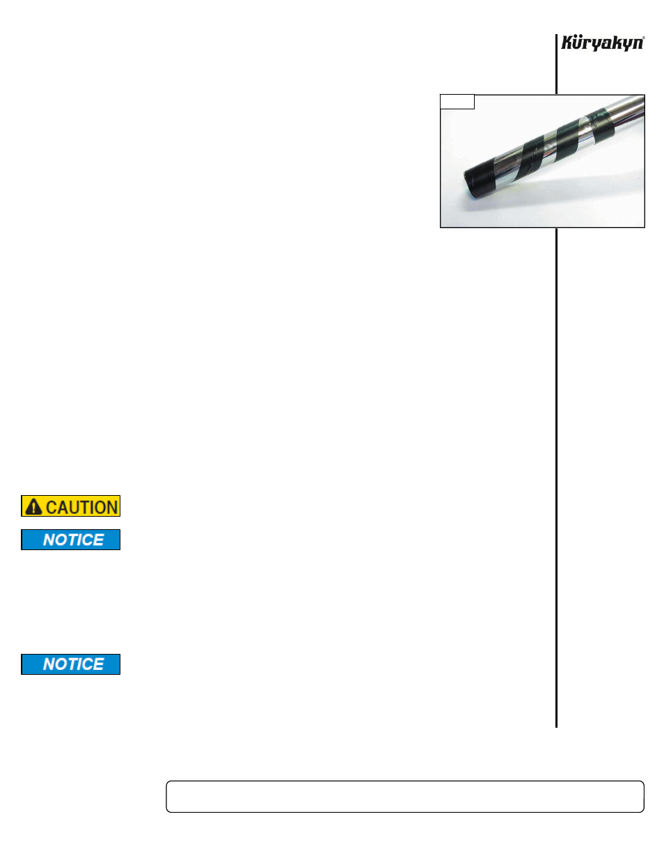
Test fit each side. The throttle side grip has a slightly larger inside diameter
than the clutch side grip. The grips should slide into place with slight
resistance. If the grips slide on too loosely, make a “barber pole” wrap around the bar or throttle
sleeve with electrical tape. PIC 1
INSTALLATION OF CLUTCH SIDE OR THROTTLE SIDE GRIP
WITH CLOSED END THROTTLE TUBE
STEP 5
This step only applies to the clutch side!
Some motorcycles have the switch
housings “pinned” in place making it impossible to relocate them. If the exposed handle bar on
the clutch side is shorter than the length of the ISO-Grip, the end rubber will not be fully
supported once installed. Measure the length of exposed handle bar on the clutch side. Measure
the depth of the left grip. Subtract the length of the handlebar from the depth of the grip; this will
give you the length of the spacer required. Using a hack saw or utility knife, cut the spacer to
length
and
deburr.
STEP 6
Insert the spacer into the clutch grip and slide it down as far as possible onto the handlebar to
push the spacer all the way to the end. On the throttle side, slide the grip on until it is up to the
switch housing. Rotate each grip to determine the orientation that is most comfortable. Make a
mental note of the location or make a non-permanent mark on the grip and/or switch housing.
Remove the grips.
Use extreme care when using the glue included with this kit. Read all
precautions and avoid contact with skin or eyes.
Cover any area of the motorcycle where the glue could possibly drip during
installation.
STEP 7
With an ammonia based cleaner or similar degreasing agent and a clean rag, wipe off the exposed
handlebar and the inside of the grip to remove any contaminates. Insert the spacer from STEP 5,
if needed, into the clutch side grip. Take the supplied tube of adhesive and squeeze a good
amount of glue onto the inner side walls of the clutch grip. Rotating the grip while applying the
glue will help distribute it evenly. Make sure you get the glue all the way to the end of the rubber
insert
in
the
grip.
The adhesive supplied sets up ALMOST INSTANTLY in the absence of air. There is
enough time to slide the grip into place, but ONCE IT STOPS MOVING, IT CANNOT
BE ADJUSTED.
STEP 8
In one smooth motion, slide the grip onto the end of the bar all the way into position. Rotate
it back and forth slightly as you slide it on to help distribute the glue evenly and keep the grip
from “plowing” the glue up against the switch housing. Once in place, squeeze the grip firmly to
press the rubber against the bar and hold for 15 seconds. Full bonding will occur in 24 hours.
UNIVERSAL ISO GRIPS
INSTALLATION
-cont.-
PIC 1