Custom tie-down brackets for victory, Tubular-style engine guard installation, Forged-style engine guard installation – Kuryakyn 938 CUSTOM TIE-DOWN BRACKETS FOR VICTORY User Manual
Page 2: Installation
PAGE
2
TUBULAR-STYLE ENGINE GUARD INSTALLATION:
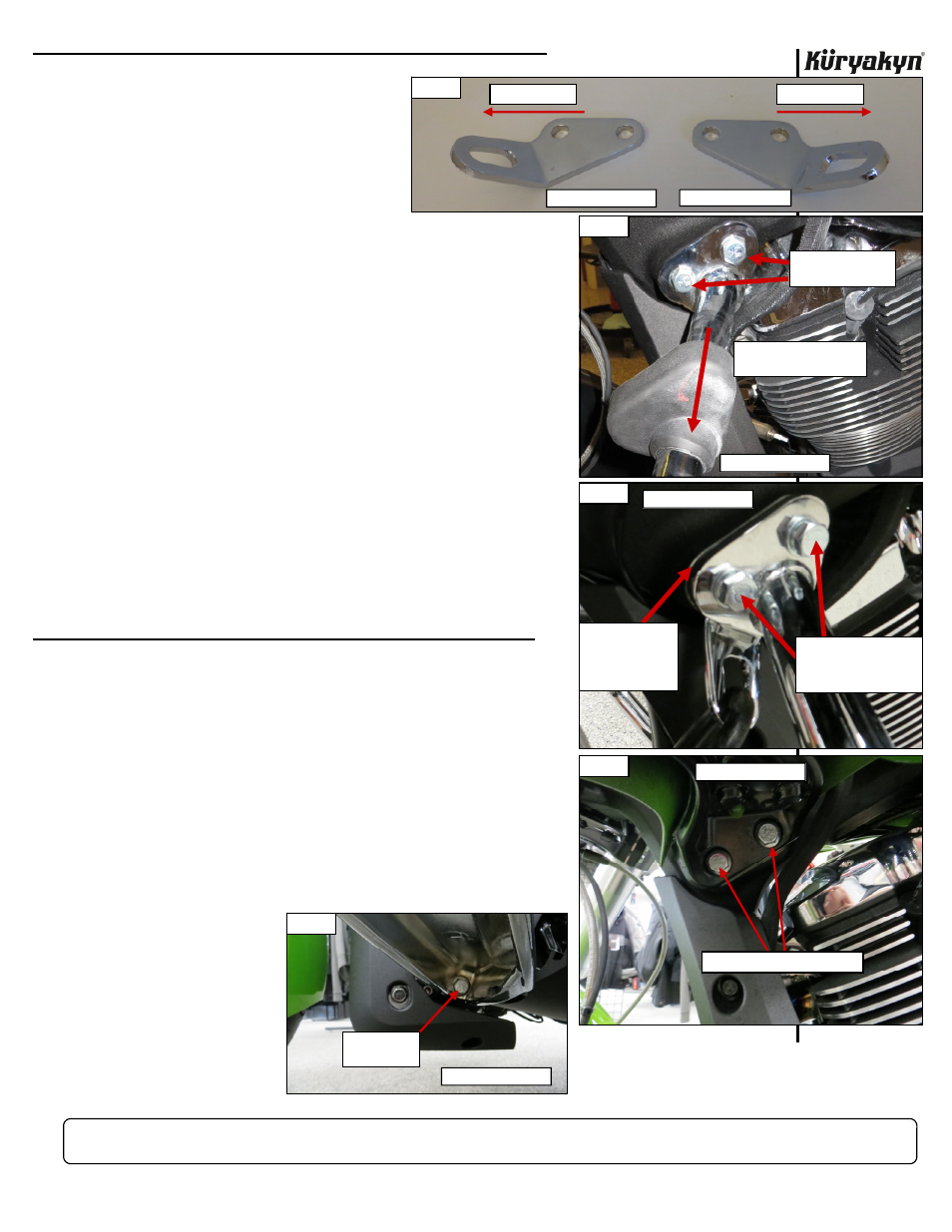
STEP 3
Determine clutch-side (left) and brake-
side (right) Tie-Down Brackets. PIC 1
STEP 4
Starting on the clutch-side, gently pull
the rubber boot (PIC 2) away from the
engine guard mount.
STEP 5
Remove the two OEM bolts shown in PIC 2.
STEP 6
Slide the clutch-side (left) Tie-Down Bracket in between the engine
guard weldment and the frame. PIC 3
STEP 7
Insert the included M10 Bolts through the Split Lock Washers,
Washers, engine guard weldment, Tie-Down Bracket and into the
frame.
STEP 8
Thread both Bolts into the frame and
torque the Bolts to 52
FT/LBS.
Slide the rubber boot back over the mount.
STEP 9
Repeat
STEPS 4 through 8 for the brake-side (right).
FORGED-STYLE ENGINE GUARD INSTALLATION:
STEP 10
Determine the left Tie Down Bracket from the right. PIC 1
STEP 11
Locate and remove the two OEM bolts in the clutch-side (left)
forged engine guard. PIC 4.
STEP 12
Locate the engine
guard’s lower mount-
ing bolt. PIC 5
Loosen the bolt. DO
NOT FULLY RE-
MOVE THE BOLT.
Loosening the bolt
will make aligning the
upper bolt holes
easier.
-cont.-
CUSTOM TIE-DOWN BRACKETS FOR VICTORY
INSTALLATION
PIC 2
REMOVE THE TWO
OEM BOLTS
SLIDE RUBBER BOOT
AWAY FROM MOUNT
CLUTCH-SIDE (LEFT)
CLUTCH-SIDE (LEFT)
PIC 3
SLIDE TIE-DOWN
BEHIND THE
ENGINE GUARD
WELDMENT AS
SHOWN
INSERT TWO INCLUDED
BOLTS WITH THE HARD-
WARE. TORQUE TO 52
FT/LBS
REMOVE THE TWO OEM BOLTS
CLUTCH-SIDE (LEFT)
PIC 4
PIC 5
LOOSEN THE
LOWER BOLT
CLUTCH-SIDE (LEFT)
PIC 1
BRAKE-SIDE (RIGHT)
CLUTCH-SIDE (LEFT)
FRONT OF BIKE
FRONT OF BIKE