Tech-connect, Installation – Kuryakyn 1788 TECH-CONNECT with CHROME PERCH MOUNT User Manual
Page 2
PAGE
2
NOTE:
For devices measuring 1-5/8” to 3-5/8” wide.
Ensure that the installation of this product does not interfere
with the proper operation of the motorcycle before riding.
Avoid damage to the motorcycle. Protect painted surfaces with a soft
cloth or blanket.
It is the installer’s responsibility to ensure that there is adequate
clearance between the Tech-Connect and any painted surfaces.
Küryakyn is not responsible for any damage due to inadequate
clearance.
Be aware of any cables/wires that could potentially be pinched or
crushed while using this product.
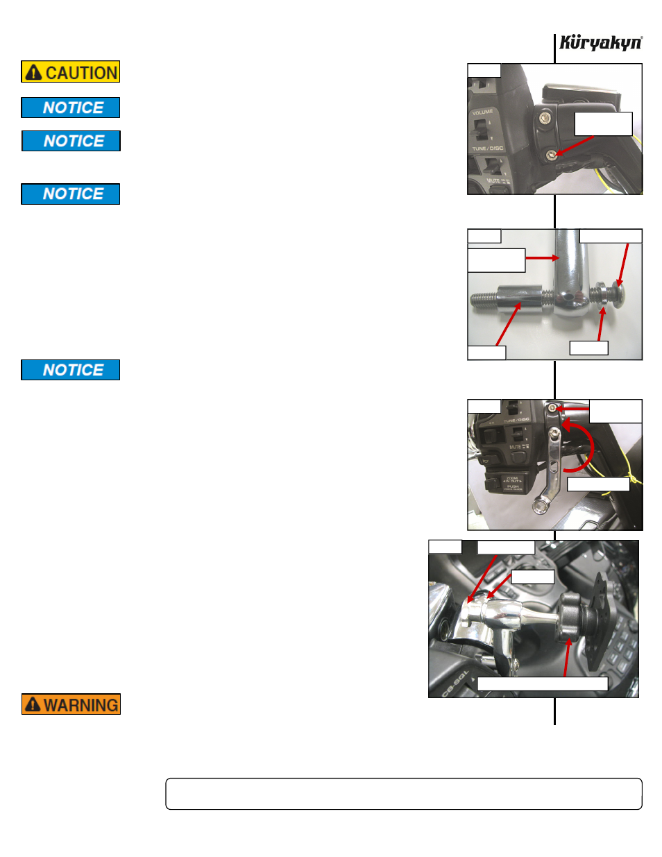
STEP 2
Place a clean, soft blanket over the gas tank to protect the paint.
STEP 3
Select either the clutch or brake perch for mounting the arm. When mounted, the
arm will usually point towards the center of the bike. Remove the bottom screw
securing the clutch or brake perch halves as shown in PIC 1; this will not be used
again.
STEP 4
Locate the correct screw, either the metric or standard, by comparing threads on
the included screws to the threads from the screw that were removed. The
1/4”-20 x 2-1/4” screws are generally used on older H-D motorcycles, the
1/4”-20 X 2” screws on newer H-D’s and the M6 X 1.0 X 55mm on Metric bikes.
Use the supplied anti-seize for fasteners; this will prevent galling and
make future removal of fasteners easier.
STEP 5
As shown in PIC 2, place the washer over the screw, then insert through the perch
mount arm and place the spacer over the screw then add a dab of anti-seize to the
screw
end.
STEP 6
As shown in PIC 3, place the arm, screw, washer and spacer on the perch and
start the screw, finger tighten for now.
STEP 7
Remove the upper screw securing the perch mounting halves; it will not be used
again.
PIC
3
STEP 8
Rotate the arm up into position and install the screw, washer, and spacer, while
using a dab of anti-seize as in STEP 5. PIC 3
STEP 9
Tighten both of the screws securely.
STEP 10
Install the Accessory Mount Plate to the perch mount by inserting the
metal shaft through the hole in the perch mount. The hex flats on the
metal shaft will line up with the hex flats in the hole. Secure the
Accessory Mount Plate with the included 1/4” flat washer, then the
1/4” lock washer, then the Thumb nut. PIC 4. Tighten securely.
STEP 11
Turn the handlebars in both directions to their full stop position and
ensure that there is clearance between the mounting plate/accessory and
the gas tank, dash and other accessories.
ENSURE THAT THERE IS CLEARANCE AT ALL POINTS
WHEN THE HANDLEBARS ARE TURNED, INSUFFICIENT CLEARANCE MAY-
CAUSE DAMAGE TO THE MOTORCYCLE OR CAN CAUSE LOSS OF CONTROL
THAT COULD RESULT IN SEVERE INJURY OR DEATH.
TECH-CONNECT
INSTALLATION
-cont.-
PIC 1
REMOVE THIS
SCREW
PIC 2
WASHER
SPACER
BUTTON SCREW
PERCH MOUNT
ARM
PIC 4
THUMB SCREW
USE TENSION NUT TO ADJUST PLATE
WASHERS
PIC 3
ROTATE ARM UP
REMOVE TOP
SCREW