Fused terminal block, Installation – Kuryakyn 2208 UNIVERSAL ACCESSORY FUSED TERMINAL BLOCK User Manual
Page 2
PAGE
2
YOU WILL BE WORKING AROUND THE ENGINE AND EXHAUST SYSTEM
DURING INSTALLATION. ENSURE THAT THE ENGINE AND EXHAUST
SYSTEM HAVE FULLY COOLED TO PREVENT INJURY.
IT IS THE INSTALLERS RESPONSIBILITY TO ENSURE THAT THE
INSTALLATION OF ACCESSORIES TO THE FUSED TERMINAL BLOCK DOES
NOT EXCEED 20 AMPS TOTAL. EXCEEDING THE MAXIMUM ALLOWABLE
(20 AMPS) AMPERAGE MAY LEAD TO CIRCUIT FAILURE WHICH COULD
RESULT IN SERIOUS INJURY OR DEATH.
IT IS THE INSTALLER’S RESPONSIBILITY TO ENSURE THAT THE
ELECTRICAL ACCESSORIES OPERATING AT ONE TIME DO NOT USE MORE
CURRENT THAN THE CHARGING SYSTEM CAN SUPPLY. OVERLOADING OF
THE CHARGING SYSTEM CAN CAUSE BATTERY DISCHARGE, DAMAGE THE
ELECTRICAL SYSTEM ON THE MOTORCYCLE AND LEAD TO CIRCUIT
FAILURE. THIS MAY RESULT IN SERIOUS INJURY OR DEATH.
Avoid potential electrical shock! Disconnect the battery before adding or
removing accessories from the Fused Terminal Block.
Avoid potential electrical shock and/or potential
battery drain! All accessories connected to the Fused
Terminal Block are connected directly to the battery
and powered at all times! These connected accessories
DO NOT lose power when the key is turned “OFF”.
STEP 2
Locate a suitable mounting location for the Fused Terminal Block. This
could be on the frame, under the seat, behind the fairing. We include a
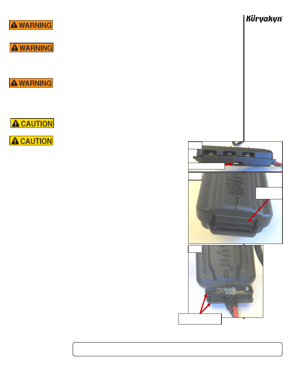
12” nylon cable tie (there is a slot on each side (PIC 1) of the Fused
Terminal Block that will allow the cable tie to pass through to secure it) or
hook and loop tape to use to secure the Block to your desired location.
DO NOT secure at this time.
NOTE:
Depending on how you decided to secure the Fused Terminal
Block to the motorcycle, the optional Protective Sleeve may or
may not fully cover the Fused Terminal Block.
STEP 3
If using the optional protective sleeve: Thread the wire harness into
the protective sleeve. Slide the protective sleeve along the wire harness
and over the Fused Terminal Block for now. With or without the
protective
sleeve: Route the wire harness from the Fused Terminal
Block in the desired location to the battery. DO NOT connect to the
battery at this time. Coil up any excess length of wire harness or cut
any excess length from the end of the wire harness. If the wire harness is
cut, remove approximately wire 1/4” of insulation from the end of each
wire. The insulator on the ring terminal should cover all exposed
wire when installed to avoid a potential short. Attach one of the
included ring terminals to each wire.
STEP 4
Open the Fused Terminal Block by pressing the latch on the end in
towards the Block. PIC 2 Open the lid far enough so the hooks on
the opposite end of the lid free from the slots on the base. PIC 3
FUSED TERMINAL BLOCK
INSTALLATION
-cont.-
PIC 1
PIC 3
PIC 2
SLOT FOR CABLE TIE
PRESS HERE TO
RELEASE LID
OPEN FAR ENOUGH TO
FREE HOOKS FROM SLOTS