Hypercharger, Installation – Kuryakyn 9420 HYPERCHARGER for YAMAHA User Manual
Page 3
PAGE
3
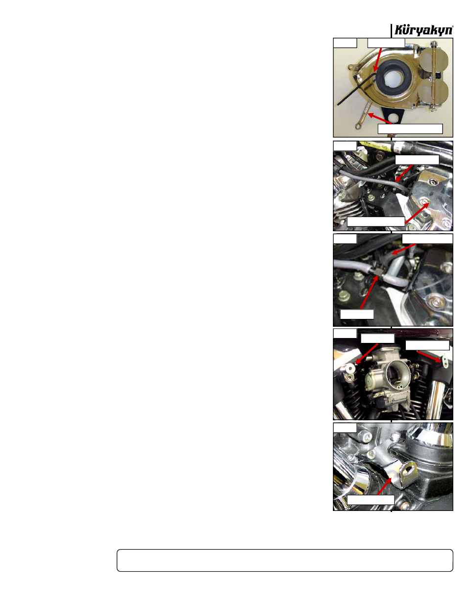
STEP 7
Line up the three holes in the back plate of the Hypercharger and the three holes in the flange of
the rubber intake duct with the three holes in the main support bracket. Insert the
three supplied 1/4”–20 x 5/8” socket head cap screws from inside the Hypercharger
and secure on the back side of the main support bracket with the 1/4”–20 thin
nylock nuts. You will need to pull back the inner flange of the rubber intake duct to
access the holes. Hold the nylock nuts with an open end wrench as you tighten the
socket head cap screws with a hex wrench. Be careful not to over tighten and
cause the rubber intake duct to pucker around the nylock nuts. See PIC.3.
STEP 8
Reinstall the trap door with its gasket on the Hypercharger.
STEP 9
Install the supplied 90-degree barbed fitting into on the back side of the
Hypercharger. The hole is located on the rearward (tapered) end of the air cleaner.
Thread the fitting in until the hex portion of the fitting is about 1/8” from contacting
the
surface.
STEP 10
Tap into the vacuum source by cutting the vacuum line shown in PIC.4. This line
comes from the top of the intake manifold near the rear cylinder head on the left
(sitting on bike) side of the bike. Install the supplied “T” fitting as shown in PIC.5.
Connect the supplied 16” length of 5/32” vacuum line to the 3rd leg of the “T”
fitting. This section of line will be routed to the Hypercharger in a later step.
STEP 11
Place the OEM clamp removed in STEP 2 on the end of the rubber intake duct in the
same manner it was installed on the OEM air duct.
STEP 12
Loosely install the “Z” Bracket to the rear cylinder head and the “L” bracket to the
front cylinder head using the supplied M6 x 1.0 x 30mm socket head cap screws.
See PIC.6. Their position may need to be adjusted slightly when the air cleaner is
installed so do not tighten them fully at this time.
STEP 13
Install the chrome lower support bracket as shown in PIC.7 using the OEM
hardware. If necessary, tweak the bracket upward slightly so it does not contact the
engine case.
STEP 14
Hold the Hypercharger and support bracket assembly up to the bike.
• Slip the rubber intake duct with the OEM clamp onto the carburetor.
• Loosely fasten at the top two legs of the “Y” bracket to the “Z” and “L” brackets.
Use the supplied M6 x 1.0 x 16mm Socket Head Cap Screws and the supplied
Tapered Bolt Caps as seen in PIC.8.
• Loosely fasten the lower leg of the “Y” bracket and idle speed adjuster bracket
using the supplied Tapered Bolt Cap and the M6 serrated nut with the OEM
fastener. See PIC.9. It may be necessary to slightly adjust the position of the “Z”
and “L” brackets in order to line up all mounting points.
STEP 15
Once all fasteners are in place, fully tighten the lower leg of the main mounting
bracket, the two fasteners that hold the “Z” and “L” brackets to the cylinder heads,
and the two fasteners that hold the main mounting bracket to the “Z” and “L”
brackets. Tighten the OEM clamp securing the rubber intake duct to the carburetor.
NOTE:
To tighten the “L” bracket to the front cylinder head, it may be necessary
to momentarily remove the main mounting bracket from the “L” bracket to
allow access to the M6 x 1.0 x 30mm socket head cap screw securing the
“L” bracket to the head.
HYPERCHARGER
INSTALLATION
-cont.-
PIC 3
PIC 4
PIC 5
PIC 6
PIC 7
HEX WRENCH
COMBINATION WRENCH
VACUUM HOSE
REAR CYLINDER HEAD
VACUUM TO HYPER
“T” FITTING
Z BRACKET
L BRACKET
LOWER SUPPORT