Hypercharger, Installation – Kuryakyn 9400 HYPERCHARGER AIR CLEANER KIT User Manual
Page 3
PAGE
3
STEP 10
Remove the brackets that held each round backing plate. The right hand bracket is also a carb
stabilizer. This function is duplicated with one of the included brackets.
STEP 11
Remove the carburetor according to the section in your factory service manual
that outlines procedures for carburetor removal, disassembly, reassembly and
installation. We recommend that you label each hose or fitting as they are
removed
to
make
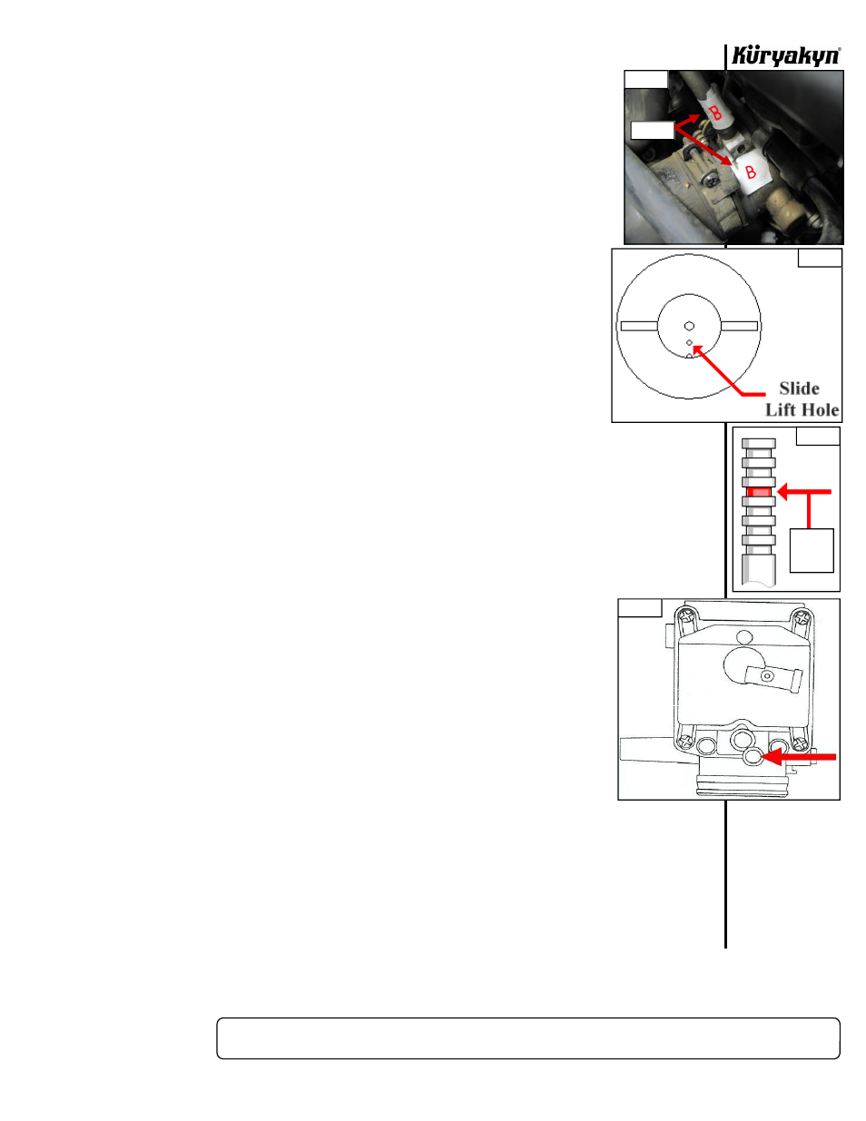
reassembly easier. An example of hose labeling is shown in PIC.1.
CARBURETOR RE-JETTING PROCEDURE
NOTE:
Different combinations of aftermarket exhaust and air cleaners will have
a significant impact on carburetor jetting. The supplied jetting
components
have
been
tested
and
found to be a good combination to
produce drivability and performance with stock or free flowing, muffled/
baffled exhaust pipes. We highly recommend NOT using drag pipes (open
style). Using drag pipes in conjunction with our air cleaner will require
additional jetting above and beyond the components included in this kit.
A) Consult your factory service manual for details of this procedure. We have supplied jets
to cover many common configurations. Remove the four Phillips head screws securing
the plastic carb top to the carb body. Carefully remove the plastic carb top making sure
not to damage the rubber diaphragm.
B) Carefully remove the diaphragm and slide from the carb.
C) Remove the spring, plastic retainer and needle from the slide.
D) See FIG.1. Very carefully drill out the slide lift hole with the included .070 drill bit. Be
sure to remove all filings from drilling. Place the small E-Clip in the third groove from the top of the
needle, See FIG.2. Stack two .020 shims on top of the E-Clip. The shims will keep the needle from
bouncing in the slide.
E) Carefully replace the needle/slide assembly into the carb body. Place the stock plastic retainer over the
end of the needle and shims. The retainer should gently seat over the shims. Place the spring over the
retainer. Carefully seat the lip of the diaphragm in the corresponding groove in the carb body.
DO NOT
FOLD, PINCH, TEAR OR PUNCTURE THE DIAPHRAGM!!
Replace the top cover.
F)
READ THIS ENTIRE STEP BEFORE PROCEEDING!
See FIG.3. Turn the carb upside down. Using the
supplied 5/32” drill bit, slowly drill out the plug covering the idle mixture screw. The mixture screw is
made of brass. If you drill to far you will destroy the slot in the adjustment screw making
adjustment impossible. Once the hole is drilled, start the supplied slotted pan screw into
the drilled hole just far enough for the threads to “bite”. Grasp the head of the screw
with a pliers and pull outward in a slight rocking motion until the plug comes free.
G)
Using a small flat head screwdriver, slow and gently turn the adjustment screw inward
(clock-wise) until it lightly bottoms out. Once lightly bottomed out, back the adjustment
screw outward (counter clock-wise) three full turns.
H) Remove the four Phillips head screws that secure the float bowl to the carb body.
Remove the float bowl being extremely careful no to disturb the position of the float.
I) Replace the stock low speed jet with the supplied #48 jet. Replace the stock main jet with
the supplied #135 jet.
CARBURETOR TUNING TIPS
• Run the bike until it reaches operating temperature. Adjust the idle mixture screw until the bike reaches
it’s highest idle speed. Reset the idle speed with the idle adjustment knob.
• If further tuning is required, let your spark plugs be your guide. A white or uncolored plug indicates a
lean condition while a black or sooty plug indicates a rich condition.
• Be sure you’re working with the correct jet. The low speed (pilot jet) affects throttle positions of about
1/8 open to approximately 1/3 open. The main jet affects throttle positions of about 3/4 open to wide
open. Needle position affects most throttle settings in between. In other words, don’t change the main jet
if you are experiencing a lean condition just off idle.
HYPERCHARGER
INSTALLATION
-cont.-
PIC 1
FIG 1
FIG 2
FIG 3
LABELS
PLACE
SHIMS
HERE