Led speaker grills for victory, Installation – Kuryakyn 7698 LED SPEAKER GRILLS FOR VICTORY User Manual
Page 2
PAGE
2
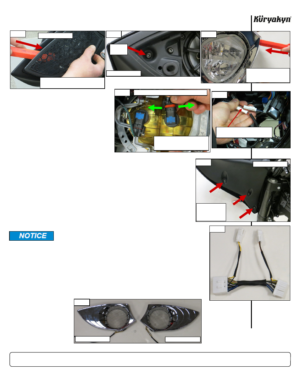
STEP 2
Use a plastic trim tool to gently pry both OEM speaker grills out of the fairing as shown in PIC 1;
start on the outside and work your way inward. Remove the screw shown in PIC 2 from both
sides; set it aside for now, it will be reused later.
STEP 3
Refer
to
PIC 3. Use the plastic
trim tool to gently pry the head-
light trim away from the fairing;
set it aside for now, it will be re-
used later. Remove the four
screws securing the headlight
assembly to the fairing; set the
screws aside; they will be reused
later.
STEP 4
Refer
to
PIC 4. Gently pry the
latches away from the tabs on
the bulb connectors; pull the connectors straight away from the bulbs. Set
the headlight assembly aside for now.
STEP 5
Refer
to
PIC 5. Locate the left and right turn signal connectors inside the
headlight area of the fairing. Depress the small tabs to separate the turn
signal connectors.
STEP 6
Remove the screws shown in PIC 6 from each side of the fairing. Grasp
the fairing by the upper edge (just below the windshield) and bottom of
the headlight opening. Pull forward on the bottom edge and then the top
to remove the outer fairing. Set the fairing on a soft sturdy surface.
STEP 7
Refer
to
PIC 7. Locate the included 14-pin Fairing “Run” Adapter in the kit. On
the inside of the inner fairing, locate and separate the black 14-pin connector on
the bike. Apply some of the included Dielectric Grease to the open connector ends
and link the Fairing “Run” Adapter in between the black 14-pin connectors.
STEP 8
Refer
to
PIC 8. Determine the clutch-side (left) Speaker Grill from the brake-side
(right).
LED SPEAKER GRILLS FOR VICTORY
INSTALLATION
Kuryakyn recommends the use of the included dielectric
grease on ALL electrical connections.
PIC 8
CLUTCH-SIDE (LEFT)
BRAKE-SIDE (RIGHT)
PIC 1
INSERT THE TRIM TOOL BETWEEN THE
GRILL AND FAIRING; GENTLY PRY OFF
CLUTCH-SIDE (LEFT)
PIC 3
INSERT THE TRIM TOOL
BETWEEN THE TRIM AND
FAIRING; GENTLY PRY OFF
PIC 2
REMOVE
SCREW
CLUTCH-SIDE (LEFT)
PIC 7
-cont.-
PIC 6
REMOVE THE
THREE SCREWS
FROM EACH SIDE
OF THE FAIRING
CLUTCH-SIDE (LEFT)
PIC 5
DEPRESS TAB TO SEPARATE THE
TURN SIGNAL CONNECTOR
PIC 4
PRY LATCHES AWAY FROM TABS
AND PULL CONNECTOR STRAIGHT
AWAY FROM BULB
VIEW OF BACKSIDE OF HEADLIGHT ASSEMBLY