Velociraptor air cleaner – Kuryakyn 9442 VELOCIRAPTOR AIR CLEANER User Manual
Page 2
INSTALLATION
PAGE
2
VELOCIRAPTOR AIR CLEANER
ATTENTION!
This indication alerts you to the fact that ignoring the contents described herein may
negatively affect product performance and functionality.
TOOLS SUGGESTED
Set of Hex Wrenches, Phillips Screwdriver, Combination Wrenches, Socket Set with Ratchet
STRICTLY OBSERVE ThE fOLLOWING GUIDELINES IN ORDER TO USE ThE PRODUCT
PROPERLY AND AVOID POTENTIALLY DANGEROUS ACCIDENTS.
DISCLAIMER
— PLEASE READ BEFORE PROCEEDING
Any modifications to a motorcycle’s exhaust or intake tract require carburetor re-jetting to achieve
maximum performance and maintain drivability. If you are uncomfortable with the process of tuning
your carburetor, we recommend that you bring your motorcycle to a qualified motorcycle mechanic
to have this kit installed. The jets included in this kit were selected based on test results with various
combinations of components that we felt would represent the majority of the customers purchasing
this kit. However, no two motorcycles are exactly alike. Depending on the individual case, additional
jets may need to be purchased from an outside source. Küryakyn warrants the parts included in this
kit to be free of defects in materials and workmanship, but makes no claim whatsoever in regard to
costs associated with installation or tuning.
PROCEDURE
STEP 1
Read and understand all steps in the instructions before starting the installation. Park
the motorcycle on a hard, level surface; turn off the ignition and allow the engine to cool.
STEP 2
Remove the seat and rear-mounting bolt on the fuel tank.
STEP 3
Prop up the rear of the tank; a small block of wood works well.
STEP 4
Remove your stock air cleaner and spark plug covers. You may want to ask a
friend to hold and lift the tank slightly as you work the air box out from beneath, slide it
toward the rear of the bike and then out.
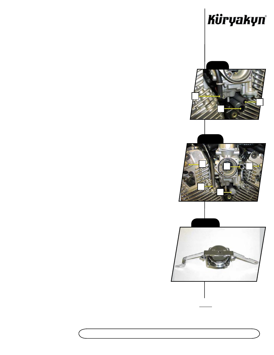
STEP 5
Remove the two hoses that are connected to the back of the air box. Take note
of the three hoses marked as “A,” “B,” and “C” in PIC.1. The hose marked as A should be
left in the metal retaining loop on the side of the carb - make sure this hose is not pinched or
kinked. The hose marked as B should be capped off using the included gray vinyl cap. The
hose marked as “C” should be routed up behind and over the top front side of the carb.
See PIC.2.
STEP 6
Remove and set aside the two bolts marked as “D” in PIC.2. They will be
reused.
STEP 7
Re-jet carburetor. Refer to factory service manual for disassembly procedure
and to the last page of this instruction for baseline recommendations. The OEM carb top
will be replaced so there is no need to reinstall it after shimming the needle.
STEP 8
Insert the two supplied 1/4”–20 X 3/8” Hex Head Cap Screws through each
side of the 90 Degree top bracket on the Chrome Carburetor Top/Inner Cup, through
the Front and Rear 26 Degree Cylinder Brackets and fasten with the supplied 1/4”
Chrome Split Lock Washers and Acorn Nuts. See PIC.3.
STEP 9
Take note of the raised boss near the front, right screw on the stock
carburetor top; the new Chrome Carburetor Top/Inner Cup also has
this raised boss
and must be installed in the same orientation. While holding the stock carburetor top
in place against the tension of the slide spring, carefully remove the four Phillips
screws securing it to the carburetor. Set the screws aside and slowly remove the
stock carburetor top allowing the slide spring extend out of the carburetor body.
Leave the slide spring in place and be careful not to disturb the slide diaphragm.
PIC. 1
A
B
C
PIC. 2
A
B
C
D
D
PIC. 3
-cont.-