Black led speaker bezels, Typical (non-boom™ audio) install, Installation – Kuryakyn 7286 BLACK LED SPEAKER BEZELS User Manual
Page 2: Step 12
PAGE
2
STEP 2
Remove the left side-cover; remove the main fuse.
STEP 3
Remove the outer fairing. Refer to the model specific service manual for more infor-
mation.
STEP 4
Refer
to
PIC 1. Remove both existing speaker and spacer assemblies; there will be
two (2) long screws (they will be reused) and one (1) short one on each side (it will
NOT be reused).
STEP 5
Peel the OEM mesh off of the speaker assemblies; remove any adhesive tape from
the front of the spacers.
STEP 6
Refer
to
PIC 2. Locate the included Right (brake-side) Mounting
Plate; Position the Plate against the inside of the inner fairing as
shown in PIC 2.
Align the screw holes with the screw bosses; using the notch on
the top of the Mounting Plate as a guide, mark the inner fairing
with a marker. Ensure that the Mounting Plate is oriented
exactly as shown in PIC 2.
STEP 7
Refer
to
PIC 3. Using a round file, remove about a 1/4” of
material from the inner fairing at the mark made in
STEP 6
;
the Speaker Bezel wiring will be routed through this notch be-
tween the Mounting Plate and inner fairing.
STEP 8
Assemble an included Speaker Mesh in the recess of the Mount-
ing Plate. The Mesh protrudes towards the rider when installed.
Set the Mesh/Plate within arms reach of the work area.
STEP 9
Refer
to
PIC 4. Locate the Left and Right LED Speaker Bezels.
Note that “LEFT” and “RIGHT” is molded into the backside.
Left = Clutch side
Right = Brake side
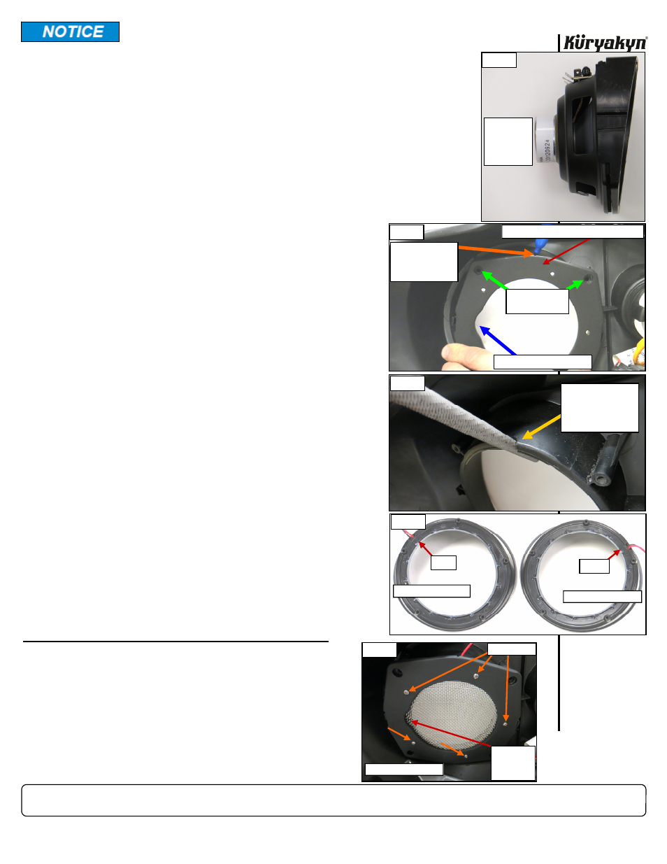
STEP 10
Refer
to
PIC 5. Position the Right LED Speaker Bezel in the
inner fairing; route the wiring through the notch; align the
Mesh/Plate with the five small screw holes in the Bezel and se-
cure with five of the included #4 screws. DO NOT OVER
TIGHTEN THE SCREWS.
STEP 11
Repeat
STEPS 6 through 10
for the other side.
BOOM!™ Audio equipped installation skip to
STEP 14
.
TYPICAL (NON-BOOM™ AUDIO) INSTALL:
STEP 12
Reinstall the right side speaker assembly using two long
screws (from
STEP 4
) and one of the included #10 X 1-
1/4” Pan Head Screws.
STEP 13
Repeat
STEP 12
for the other side.
DO NOT
OVER-TIGHTEN THE SCREWS!
Skip ahead to
STEP 18 or 20
(depending on model
year).
BLACK LED SPEAKER BEZELS
-cont.-
INSTALLATION
Avoid damage to the motorcycle. Protect painted surfaces with a soft cloth
or service cover.
PIC 1
TYPICAL
SPEAKER
AND
SPACER
ASSEMBLY
AT THE MARK, USE A
ROUND FILE AT AN
ANGLE TO MAKE A
NOTCH IN THE
INNER FAIRING
PIC 3
MARK THE INNER
FAIRING AT THE
NOTCH IN THE
MOUNTING PLATE
PIC 2
ALIGN HOLES
WITH BOSSES
BOOM!™ AUDIO CUT-OUT
LEFT
RIGHT
PIC 4
BRAKE-SIDE (RIGHT)
CLUTCH-SIDE (LEFT)
BRAKE-SIDE (RIGHT) MOUNTING PLATE
PIC 5
BRAKE-SIDE (RIGHT)
BOOM™
AUDIO
CUT–OUT
#4 SCREWS