Driving light and relay kit, Installation – Kuryakyn 2202 UNIVERSAL DRIVING LIGHT AND RELAY KIT User Manual
Page 2
PAGE
2
NOTE:
This is a universal kit. It is not made for any specific motorcycle application. A
significant amount of wire may be trimmed off of this harness for the
neatest installation. The female bullet type connectors (installed) aren’t
intended to mate with any connectors on any Küryakyn driving light.
NOTE:
To avoid an excess of wire, lay out your proposed routing first. Trim off
any excess wire. This will not only make the wiring easier, but it will
make a cleaner looking job when the installation is complete.
YOU WILL BE WORKING AROUND THE ENGINE AND EXHAUST
SYSTEM DURING INSTALLATION. ENSURE THAT THE ENGINE
AND EXHAUST SYSTEM HAVE FULLY COOLED TO PREVENT
INJURY.
IT IS THE INSTALLERS RESPONSIBILITY TO ENSURE THAT
THE INSTALLATION OF THIS ACCESSORY DOES NOT EXCEED
THE MAXIMUM AMPERAGE OF THE CHOSEN CIRCUIT.
EXCEEDING THE MAXIMUM ALLOWABLE AMPERAGE MAY
LEAD TO CIRCUIT FAILURE WHICH COULD RESULT IN
SERIOUS INJURY OR DEATH.
A FACTORY SERVICE MANUAL WILL BE HELPFUL IN
PERFORMING THIS INSTALLATION. DO NOT ATTEMPT TO
PERFORM THIS INSTALLATION IF YOU ARE NOT CONFIDENT
IN YOUR ABILITY TO COMPLETE ALL OF THE STEPS IN THE
PROCEDURE; CONSULT A TRAINED TECHNICIAN. IMPROPER
INSTALLATION COULD RESULT IN SERIOUS INJURY OR
DEATH.
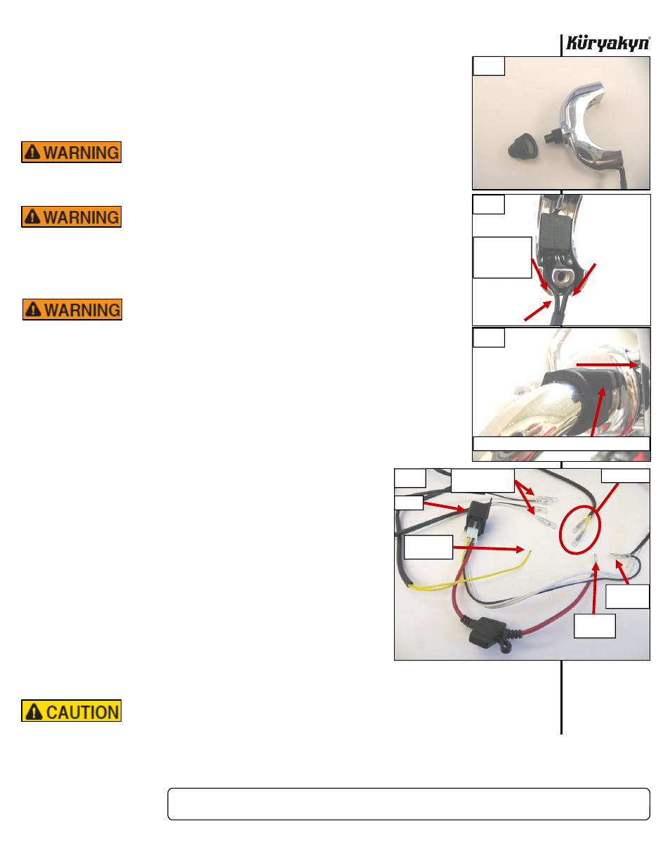
STEP 2
Install switch into front clamp half. Secure with rubber boot from outside of clamp.
PIC 1 Carefully Route wires around boss (one on each side) and exit through notch
on bottom of clamp. PIC 2
STEP 3
Determine the correct handlebar rubber insulator of the three included (either the
7/8”, 1” or 1-1/4”) for your handlebars. Locate a convenient
place on the bars for the switch to be mounted and install the
handlebar rubber insulator there with fingers on top and pointing
towards
rider.
PIC
3
STEP 4
Place front clamp half over rubber insulator so fingers slide into
notches in clamp. Place rear clamp half over insulator and attach
to front half with #8-32 X 3/4” socket head cap screws. Make
sure wires exit through notch on bottom and are not pinched.
Tighten
securely.
STEP 5
Identify the stock wiring harness; refer to your factory service
manual to locate the harness.
STEP 6
Using a test light or wiring schematic, with the key in the “ON”
position, locate a “keyed” 12-volt power wire (a wire that has
power with the key “ON” and loses power with the key
“OFF”)to power the driving lights. Once you have located a
“keyed” 12-volt power source, turn the key to the “OFF”
position and disconnect the battery.
Avoid potential electrical shock! Disconnect the battery before starting this
procedure.
DRIVING LIGHT AND RELAY KIT
INSTALLATION
-cont.-
PIC 1
FINGERS ON TOP AND POINTED TOWARDS RIDER
PIC 2
PIC 3
ROUTE WIRES
AROUND BOSS
AND THROUGH
NOTCH
PIC 4
TO “KEYED”
POWER
BATTERY
POSITIVE
BATTERY
NEGATIVE
TO SWITCH
WHITE DRIVING
LIGHT POWER
RELAY