Programming running lights as on or off – Kisan Electronics VL-20 User Manual
Page 7
Page- 5
Next, you have to locate appropriate wires on your bike. Use a voltmeter
to identify each wire, and chose an convenient location to snap the
scotch-lock over the wire and then use pliers to squeeze it tight. The small
ring connector must be inserted fully into the slot of the scotch-lock.
Typical wire colors for most
makes of bikes are shown
here as a reference only.
Be advised that color
codes can change with
models and years, so you
should verify with a
voltmeter or a test light.
PROGRAMMING Running Lights as ON or OFF
`
Hold Right Turn switch, apply & Hold brakes then turn the ignition on.
- vectraLIGHT flashes (3) times to confirm the new setting
- this is a toggle function - you can keep going back-n-forth
PROGRAMMING Running Lights as BRAKE LIGHTS
` Hold Left Turn switch, apply & Hold brakes then turn the ignition on.
- vectraLIGHT flashes (5) times to confirm the new setting
- this is a toggle function - you can keep going back-n-forth
Above programming applies to the Left and Right turn signal LEDs only.
Flashing all (16) LEDs as brakes is permitted as long as the turn signals
are NOT active.
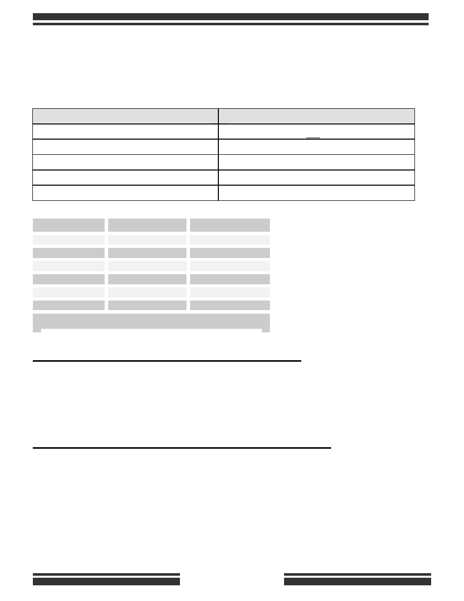
(5) INPUTS & COLORS OF LPC-16
FUNCTIONS OF BIKE’S WIRING
BLUE - POWER INPUT
12-volt with ignition ON
YELLOW - LEFT TURN SIGNAL INPUT
12-volt flash signal (high-side of bulb)
GREEN - BRAKE INPUT
12-volt from brakes (ON with brakes)
RED - RIGHT TURN SIGNAL INPUT
12-volt flash signal (high-side of bulb
BLACK - GROUND
Chassis ground connection
Right Signal
Left Signal
Honda
Orange
Light Blue
BMW
Blue/Red
Blue/Black
Triumph
Green
Gray
Suzuki
Orange
Light Blue
Kawasaki
White
Black
Yamaha
Brown
Green
Colors shown are most common for the bikes listed. You should
consult your own Manual or use a multi-meter or test light to