Vl-20 installation – Kisan Electronics VL-20 User Manual
Page 14
Page- 12
VL-20 INSTALLATION:
vectraLIGHT (VL-20) model is a turn signal and stop-light LED array.
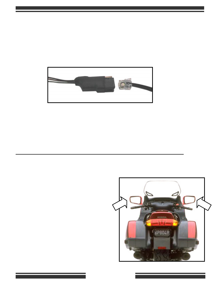
Each unit plugs into a breakout adapter, which needs to be hooked-up to
the bikes wiring. There is a label to indicate the right and left side array.
Red LEDs face the rear.
In turn signal mode, the (5) front facing Amber LEDs and the (5) rear
facing Red LEDs flash sequentially. With the brakes applied the rear
facing Red LEDs stay on with full brightness.
The Running Light mode is programmable to be OFF or ON.
Before you mount the units, consider how you will route the cable.
Routing the cable to make connections will depend on whether the side-
view mirrors are stalk mounted or attached to the fairing.
If stalk mounted, use wire-ties to
secure the cable - allowing for
appropriate slack so that the mirror
can be moved freely.
If attached to the fairing, locate an
opening through which the RJ-11 plug
can slide in.
Avoid sharp metal edges, hot
exhaust pipes and high voltage spark
plug wires, as you route the cable.