Kisan Electronics VL-20 User Manual
Page 16
Page- 14
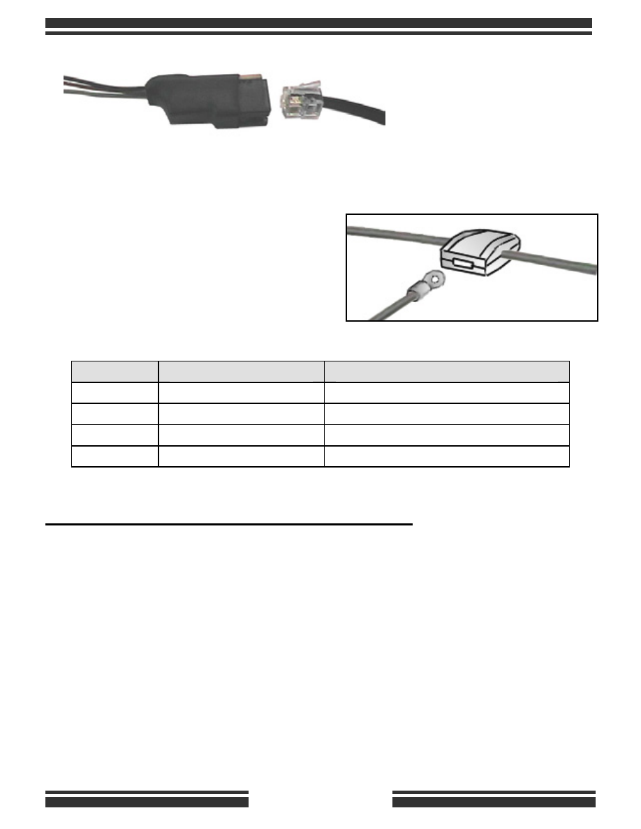
Each vectraLIGHT has
an RJ-11 4-pin plug at the
end of the 6’ long cable.
This 4-pin plug is inserted
in to a breakout adapter
as shown here.
The wires of the adapter can be connected using the scotch-locks. Use a
voltmeter to identify each wire, and
chose an appropriate location to snap
the scotch-lock over the wire and then
use pliers to squeeze it tight. The
small ring connector must be inserted
fully into the slot of the scotch-lock.
PROGRAMMING THE RUNNING LIGHT MODE:
Each vectraLIGHT unit is factory set for the Running Lights Mode to be
ON. If you wish to turn it OFF:
X
Apply and HOLD the brakes, then turn ignition ON (3) times quickly
Y
Leave the ignition ON the 3
rd
time
Z
As soon as the vectraLIGHTs flash, pump the brakes (5) time rapidly.
If you repeat the above procedure, it will turn the Running Light mode
back ON.
Wire Color
RJ-11
ADAPTER
WHITE
TURN SIGNAL INPUT
12-volt flash signal (high-side of bulb)
BLACK
BRAKE INPUT
12-volt from brakes (ON with brakes)
RED
POWER INPUT
Constant 12-volt with ignition ON
GREEN
GROUND Chassis
ground connection