Warning – Burnham BOILERS User Manual
Page 16
16
2. TEMPERING OF HOT WATER — Installation of
an automatic mixing valve will lengthen the
delivery of the available hot water by mixing some
cold water with the hot. This prevents the possibil-
ity of scalding hot water at the fixtures. In addition,
savings of hot water will be achieved since the user
will not waste as much hot water while seeking a
water temperature. Higher temperature hot water
required by dishwashers and automatic washers is
possible by piping the hot water from the heater
prior to entering the mixing valve. The mixing
valve should be “trapped” by installing it below the
cold water inlet to heater to prevent lime formation
in the valve. Refer to Figure 11.
3. FLUSHING OF HEATER — All water contains
some sediment which settles on the inside of the
coil. Consequently, the heater should be periodi-
cally backwashed. This is accomplished by install-
ing hose bibs as illustrated and allowing water at
city pressure to run into hose bib A, through the
heater, and out hose bib B until the discharge is
clear. The tees in which the hose bibs are located
should be the same size as heater connections to
minimize pressure drop.
4. HARD WATER — A water analysis is necessary
to determine the hardness of your potable water.
This is applicable to some city water and particu-
larly to well water. An appropriate water softener
should be installed based on the analysis and
dealer’s recommendation. This is not only benefi-
cial to the tankless heater but to piping and fixtures
plus the many other benefits derived from soft
water.
THE FOLLOWING GUIDELINES SHOULD BE
FOLLOWED WHEN PIPING THE TANKLESS HEATER:
1. FLOW REGULATION — If flow through the
heater is greater than its rating, the supply of
adequate hot water may not be able to keep up with
the demand. For this reason a flow regulator
matching the heater rating should be installed in
the cold water line to the heater. The flow regulator
should preferably be located below the inlet to the
heater and a minimum of 3’ away from the inlet so
that the regulator is not subjected to excess tem-
peratures that may occur during “off” periods when
it is possible for heat to be conducted back through
the supply line. The flow regulator also limits the
flow of supply water regardless of inlet pressure
variations in the range of 20 to 125 psi.
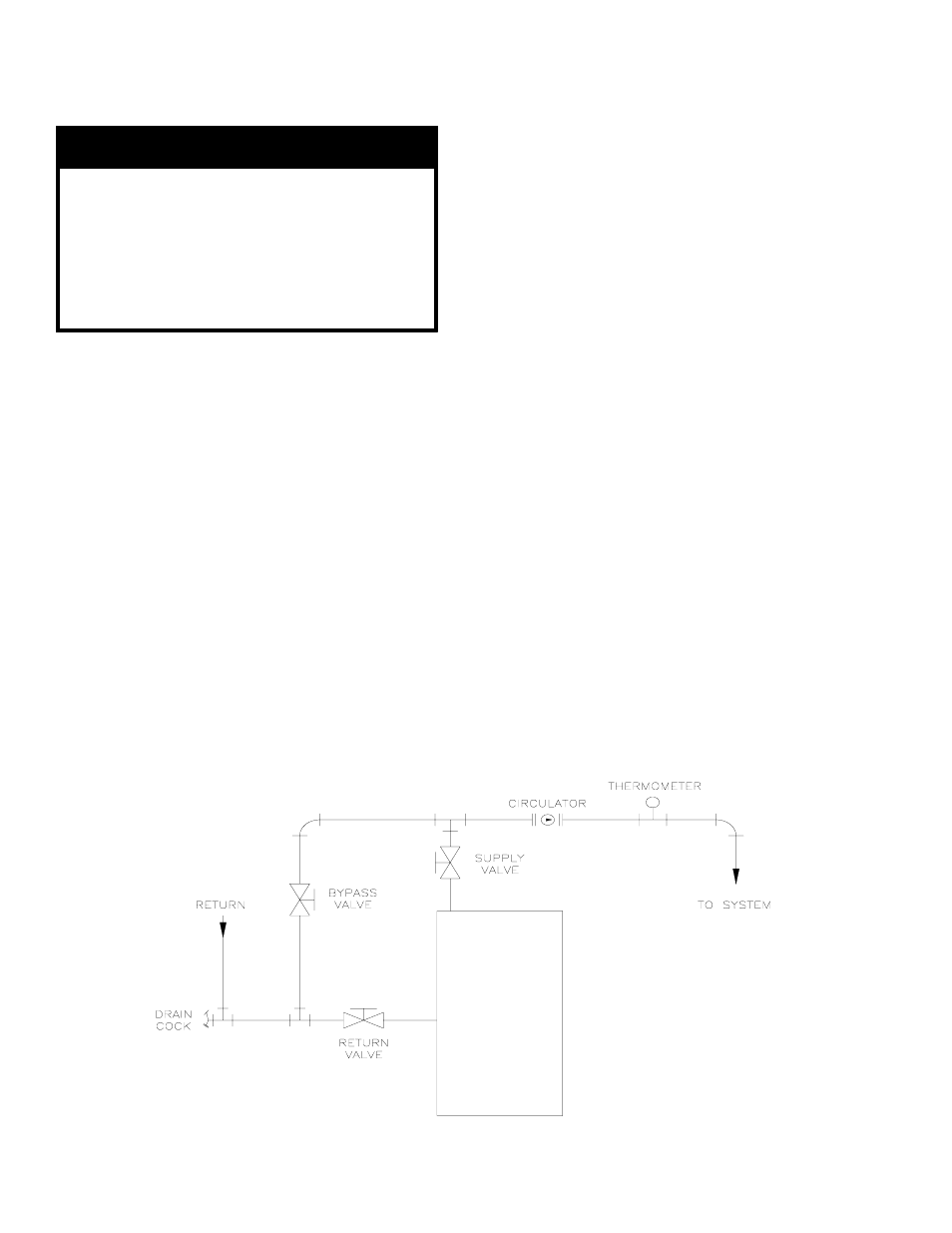
Figure 10: Recommended System Bypass Piping
F
. CONNECT TANKLESS HEATER PIPING AS
SHOWN IN FIGURE 11. See Table 1 for Tankless
Heater Rating.
WARNING
I nstall automatic mixi ng v alve at tankl ess
hea ter outle t to av oid ris k of burns or
scaldi ng due to ex cessive ly hot water at
fixtures. Adjus t a nd ma intain the mixing
valv e in accordance wi th the ma nufa cturer's
instructions. Do not operate tankl ess
heater without mixing val ve.