Installation – JULABO FLW1703 Recirculating Coolers User Manual
Page 16
16
5. Installation
Rear view:
Place the unit on an even surface on a base made of nonflammable
material.
Cooling machine, pump motor and electronics produce intrinsic heat
that is dissipated via the venting openings.! Never cover these
openings!
Keep at least 20 cm of open space on the front and rear venting grids.
Do not set up the unit in the immediate vicinity of heat sources and do
not expose to sun light.
16
A
M
P
16
A
M
P
IN
OU
Example: FL1201 (air cooled)
IN
OUT
1
6
A
M
P
1
6
A
M
P
I
N
OU
T
min
Example: FL1703 (watter cooled,
pressure, adjustable 0,5 ... 3, 0 bar)
IN
OUT
12 mm inner dia.
Example:
PVC-tubing
The place of installation should be large enough and
provide sufficient air ventilation to ensure the room
does not warm up excessively because of the heat the
instrument rejects to the environment.
For a fault (leakage) in the refrigeration system, the
standard EN 378 prescribes a certain room space to be
available for each kg of refrigerant.
> For 0.52 kg of refrigerant R-404A, 1 m
3
of space is
required.
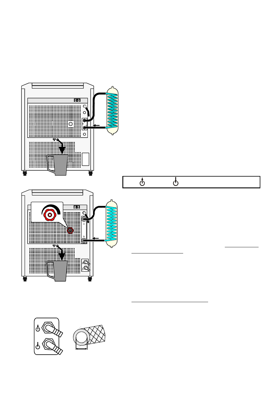
Connect the tubings for cooling the external system to
the pump connectors M16x1 for feed and return (14)
on the rear of the recirculating cooler.
- Feed
– Return
Connect a piece of tubing to the overflow connector
(15) and drain into a suitable vessel, which always has
to be placed lower thant the exit „Overflow“.
Turn the adjusting valve (14) counter-clockwise to set
the lowest manometric pressure.
Before operating the unit after transport, wait about one
hour after setting it up. This will allow any oil that has
accumulated laterally during transport to flow back
down thus ensuring maximum cooling performance of
the compressor.
Only water cooled models - FLW:
Ensure circulation of cooling water by connecting the
tubing to cooling water inlet (IN)and outlet (OUT) on
the rear (16) of the recirculating cooler.
Cooling water see page 13.
Cooling water connectors
G3/4" external thread
Tubing 12 mm inner dia. tubing
IN
Cooling water inlet
OUT Cooling water outlet