Maintenance, Innovative fluid power, 1 disassembly – HYDAC SK 600 User Manual
Page 4: 2 testing and cleaning, 3 assembly
Maintenance
INNOVATIVE FLUID POWER
52
PN#02068195 / 04.13 / ACU1102-1326
8. Disassembly, Inspection and Assembly
8.1 Removal From System
•
Carefully clean the area around the end caps on the gas
and fluid side.
•
On backup type piston accumulators the nitrogen feed line must
be isolated by means of the shut off valve.
•
Completely release the pressure on the fluid side of the
accumulator. This causes the piston to move down to the end
cap on the fluid side with the aid of the gas precharge pressure.
•
Connect the charging and gauging unit according to the
operating instructions and section 6.2. and release the pressure
slowly by opening the pressure release valve.
•
Remove all non pressurized lines on the gas and fluid side and
remove the complete piston accumulator from the system.
8.1.1 Disassembly
Further disassembly should be carried out in a suitable, clean area.
•
Clamp piston accumulator to a work bench and remove the gas
valve and all adapters and accessories.
•
Unscrew end caps on the gas and fluid side. This can be
achieved by using 2 bolts or threaded rods positioned opposite
each other. On large end caps an extension rod can be used.
•
If the end cap is in two parts, then the connection screws
between the threaded ring and end cap must be loosened first.
Unscrew the threaded ring by approximately 3 turns and screw
in the connection screws again. This pulls the end cap out.
Carry out this process several times until the end cap is
completely free.
•
Push the piston out of the accumulator in the direction of the
fluid side
(use suitable plastic or wooden rod and a rubber mallet)
.
Both threaded bores in the piston can be used for this purpose.
8.1.2 Testing and Cleaning
a) Cylindrical tube
Carefully clean the inside of the cylindrical tube (piston body) with
a non aggressive, non abrasive cleaning agent and then dry with
a lint free cloth. Check the inside of the tube for rough spots and
grooves. If these are found, it is possible for HYDAC to remachine
the cylindrical tube within certain tolerances.
If any external or internal damage is found, the pressure vessel must
be submitted to the manufacturer and, if applicable, the appropriate
inspection authority for assessment.
b) End caps
Carefully clean the end caps and replace both O–rings.
c) Piston
Remove all seals and guide rings and clean the piston thoroughly.
8.1.3 Assembly
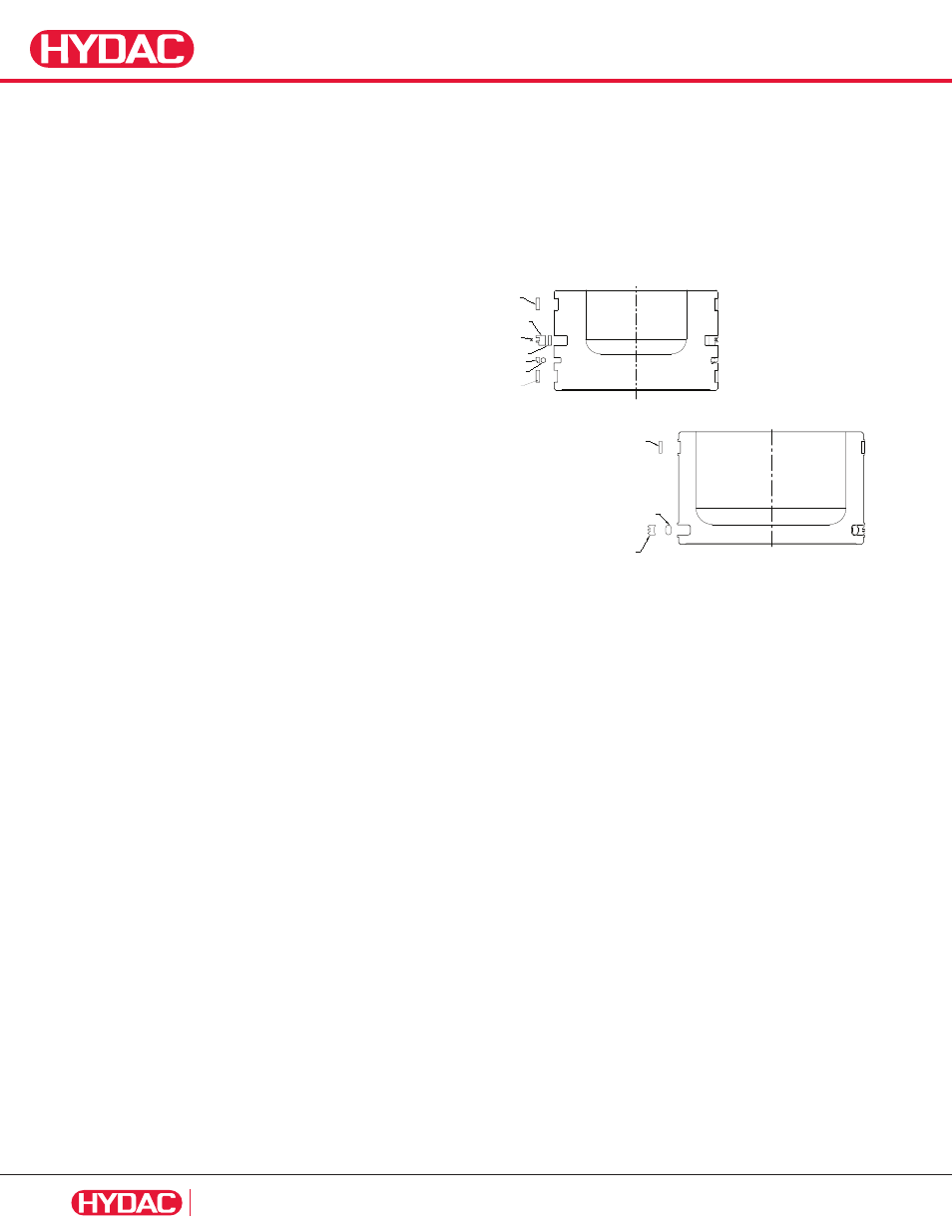
a) Fitting the piston seals
Piston design type 2:
•
Guide the mounting sleeve
(see point 9 – Special tools and spare
parts)
over the piston from the fluid side as far as the groove
provided for the center seal
(see part of center seal)
.
•
Draw the elastomer ring over the sleeve into the groove provided.
Then heat the center seal ring to 150°C to facilitate fitting and
push it over the mounting sleeve into the designated position
(shoulder towards the oil side)
. This process must be completed in
10 to 15 seconds.
•
Push the quadring into the recess of the seal ring
(see figure)
.
•
Withdraw the mounting sleeve as far as the groove for the seal
ring and fit elastomer O-ring. Then heat the seal ring to 150°C to
facilitate fitting and press into the designated position over the
mounting sleeve
(shoulder towards the oil side)
. This process must
be completed in 10 to 15 seconds.
•
Fit guide rings both on the gas as well as the oil side with the
ends displaced by 180°.
Piston design type 3:
•
Fit elastomer O-ring into the designated groove and then draw
the seal ring over it.
•
Fit guide rings both on the gas as well as the oil side with the
ends displaced by 180°.
b) Fitting the piston
•
Lubricate the upper area of the cylinder wall and the guide ends
of the piston with a suitable lubricating agent
(filtered operating
fluid)
. Do not use grease or water - water is not a lubricant!
•
Place mounting sleeve
(see section 9 - Special tools and spare parts)
onto the cylindrical tube.
•
With the hollow side towards the gas connection, insert the
piston fully into the tube. A plastic or wooden rod or a rubber
mallet can be used for this purpose.
•
Grease both O-rings and the threads on the end caps.
•
Screw both end caps, or end caps with threaded ring, into the
cylindrical tube, if necessary with the aid of the two bolts and a
rod, until they are level with the ends of the accumulator.
•
If specified, the accumulator must be filled on the gas side with
the designated quantity of oil.
•
Fit the gas valve and all adapters and other accessories.
•
Connect HYDAC charging and gauging unit and charge the
accumulator according to the instructions
(see section 6.2)
with
the required precharge pressure.
•
On piston accumulators with the gas valve version 1, the internal.
hex. screw must be tightened to a torque rating of 20 Nm and
with version 4, the valve seal cap must be tightened to a torque
rating of 30 Nm.
•
Screw on valve protection cap.
c) Fitting the accumulator into the system
Reconnect the piston accumulator to the system and check for leaks
according to section 6 - Inspection and Maintenance.
Guide ring
Elastomer ring
Seal ring
PISTON TYPE 3
Exploded view
Assembled view
Fluid side
Gas side
Gas side
Fluid side
Assembled view
Exploded view
PISTON TYPE 2
Guide ring
Ptfe seal
Quad ring
Elastomer ring
Ptfe seal ring
O-ring
Guide ring