Maintenance, Innovative fluid power, Installation and mounting 3.1. mounting position – HYDAC SK 600 User Manual
Page 2: Mounting, Connection, Venting, Safety precautions, Inspection and maintenance
INNOVATIVE FLUID POWER
50
PN#02068195 / 04.13 / ACU1102-1326
3. Installation and Mounting
3.1. Mounting Position
The piston accumulators can be mounted in any position. However,
the vertical mounting position with the gas valve at the top is
generally preferred.
Sufficient clearance must be left to mount and disconnect the
piston accumulator. In particular, an area of at least 150 x 150 x 150
mm must be left above the gas valve for fitting and operating the
charging and gauging unit.
3.2. Mounting
In accordance with the recommendations of the HYDAC brochure
“Mounting Components”, HYDAC piston accumulators must be
mounted vibration free using clamps and base brackets.
Note:
Mounting elements must never be welded to the
piston accumulator.
4. Connection
The connection of the accumulator to the system must be
stress free and torque free.
It must be possible to isolate the accumulator from the pressurized
hydraulic system.
5. Commissioning and Safety Precautions
5.1 Commissioning
Prior to connecting the accumulator to the pressurized system, the
precharge pressure should be rechecked. If the accumulator was
precharged at HYDAC the pressure level can be found on the label.
The level of the precharge pressure generally depends on the
following criteria:
•
type of system,
•
expected changes in operating temperature,
•
intended function of the accumulator.
The following precharge pressures are recommended:
for energy storage:
p
0,tmax
≤ P1 - 5 bar
p
0,tmin
≥ 2 bar
for volume compensation:
p
0
= static pressure of the system
Further information on the gas precharge pressures can be found in
the HYDAC accumulator brochure “Piston Accumulators”. Charging
and gauging of the precharge pressure is described in Point 6
“Inspection and Maintenance”.
Maintenance
5.2. Venting
Prior to commissioning, the accumulator must be vented on the oil
side. Then apply the maximum operating pressure to the complete
hydraulic system and check for leakages.
5.3. Safety Precautions
IMPORTANT!
Only use nitrogen to charge the accumulator, never
oxygen or compressed air
(risk of explosion)
.
If the pressure of the nitrogen bottle is higher than
the permissible operating pressure of the accumulator,
a pressure regulating valve must be fitted.
6. Inspection and Maintenance
On the whole, nitrogen losses on piston accumulators are very low.
However, it is advisable to check the precharge pressure p
0
at least
once during the first week following commissioning so that larger
nitrogen losses can be detected immediately. During the course of
the first two months check the precharge pressure every two weeks,
and thereafter every four weeks. If after this period no pressure
change is detected, an annual check of the nitrogen pressure is
sufficient.
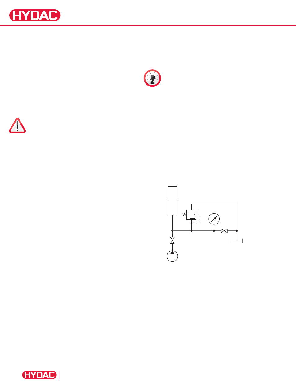
6.1. Checking the Nitrogen Pressure without
a Charging and Gauging Unit
In this case, as shown in the following drawing, a pressure gauge is
connected to a line which is directly connected to the accumulator.
E
A
Isolate the fully charged piston accumulator from the hydraulic
system by closing the shut off valve A. Slowly discharge the
accumulator on the fluid side via drain valve E. The pressure gauge
must be constantly monitored during this process. A slow, steady
pressure drop is displayed. The pressure only drops abruptly when
the accumulator has been completely discharged. The pressure
displayed before the drop corresponds to the precharge pressure
of the piston accumulator. If this pressure lies below the permissible
value, the charging procedure must be carried out, as described in
the following section.