Humanscale Float Assembly User Manual
Page 2
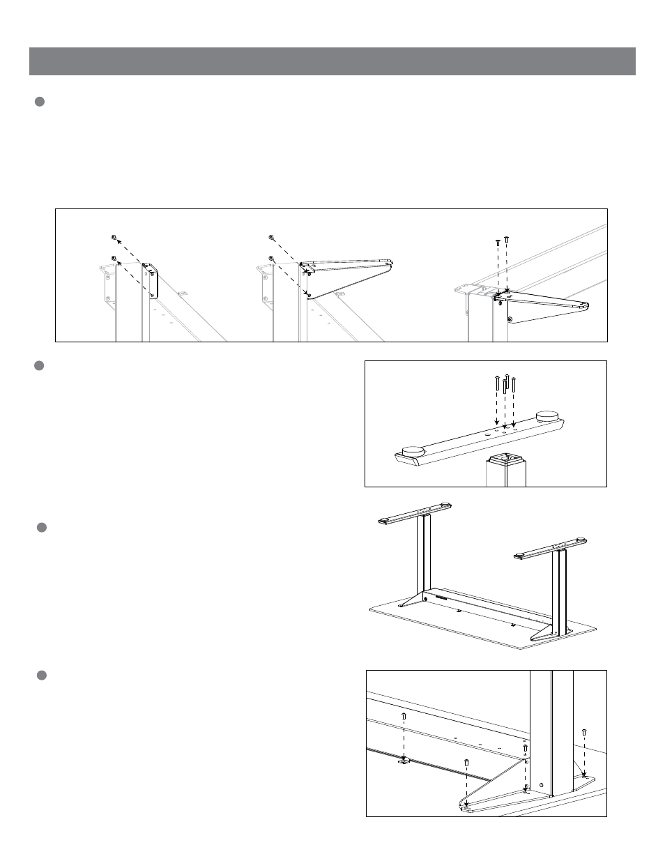
Installing the Float Wing Brackets
a. Remove the two machine screws on each end of the center beam (fig. A)
Important: The machine screws that should be removed are the ones on the same side as the spring tension
min – max scale
b. Install each Bracket on its respective table side by screwing the two machine screws through the Wing Bracket and
back into the center beam (fig. B)
c. Install the (4) M6 Short Flat Head Machine Screws through the top of the Wing Brackets and into the Float Base (fig. C)
Installing the Float Feet
a. Turn the Float Base upside down so that the center beam
is on the floor while the Float Feet are being installed
b. Install the Feet by lining up each of the four holes over the
top of the legs
Important: The longer section of the Feet must be on the
same side as the spring tension min – max scale
c. Use (4) M8 Long Machine Screws to secure each Foot to
the Base frame (fig. D)
Turn the Float Base upside down (if it is not already) and
place onto the underside of the work surface
a. Ensure that all mounting holes on the Float Base line up
with the pre-drilled metal inserts on the underside of the
work surface
b. With the Float Base in position, use the (12) M6 Short
Machine Screws to secure the Float Base to the
work surface (fig. E)
Installing the Release Paddle
a. Line up the Release Paddle with the corresponding pre-drilled metal
inserts on the underside of the work surface
b. With the Release Paddle in position, use the (4) M5 Long Machine
Screws to secure the Release Paddle to the work surface (fig. F)
Important: Do not over tighten the Release Paddle
Installing the Mounted Spring Tension Adjuster
(if you did not order your Float with this option, please proceed to step 7)
a. Take the Mounted Spring Tension Adjuster and locate the metal shaft
into the hex spigot on the center beam
b. Line up the Mounted Spring Tension Adjuster with the corresponding
pre-drilled metal inserts on the underside of the work surface
c. With the Mounted Spring Tension Adjuster in position, use the (4) M5
Short Machine Screws to secure it to the work surface
d. Take the Mounted Spring Tension Adjuster Plastic Housing, place and
snap into position over the (4) M5 Short Machine Screws that were
installed in step 6c (fig. G)
Place the work surface face down on a soft surface
to avoid scratching it
1
2
3
4
5
6
Assembly Instructions for Humanscale pre-drilled work surfaces
A
D
F
G
H
E
B
C
You will now be able to operate your new Float by gently squeezing the Release Paddle and supporting the
work surface as you raise and lower it
Carefully turn the Float back over and into position so that it is
ready to use
7
Remove the Safety Leg Pin on the right side (to the right of the
min – max scale) by removing the red tape and pulling it out
(this is used for shipping purposes only) (fig. H)
8
9
2