Humanscale ParaFlex 2 User Manual
Step 8: adjustment instructions
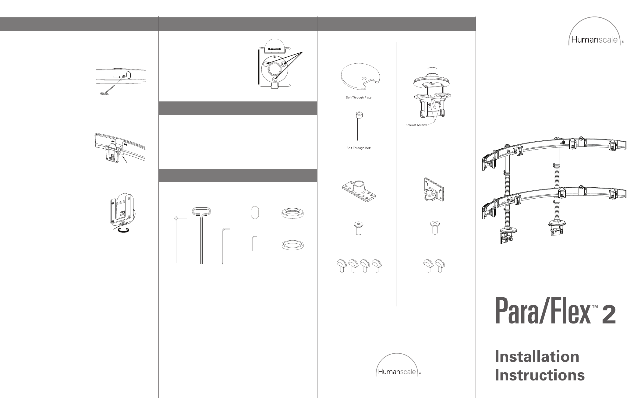
PARA/FLEX 2 INSTALLATION HARDWARE
FRICTION ADJUSTMENTS
MOUNTING OPTIONS
EXPANDING/COLLAPSING CROSSBAR
After prolonged use, the Ball
Joint Swivel/Tilt Mechanism may
require increased friction. This
can be achieved by tightening the
3 Ball Joint Friction Screws (A)
using Hex Key C.
a. Unfold Crossbar Wings to accommodate 3 or 4 monitors per row.
b. Fold away Crossbar Wings to hide behind 1 or 2 monitors.
www.humanscale.com
Hex Key A (8mm)
Hex Key C (4mm)
Hex Key D (2mm)
Vertical Assembly Cap
Crossbar Cap
Vertical Assembly
Flat Bearing
Hex Key B (5mm)
HSIPF2091
2
STEP 8: ADJUSTMENT INSTRUCTIONS
Crossbar Height Adjustment
Remove all but center monitor.
While holding Second Row Crossbar,
loosen bottom Clamping Screws (A)
slowly.
Lower Second Row Crossbar to
desired height.
Continue holding Second Row
Crossbar and tighten Clamping
Screws.
Lateral Monitor Adjustment
Push Glider Assembly (B) to desired
location.
Individual Monitor Fine Tune
Adjustment
Raise and lower individual monitors
by turning Adjustment Screw (C)
located under each Ball Joint.
Using Hex Key C, turn Adjustment
Screw clockwise to raise the height of
the monitor and counterclockwise
to lower the height.
Note: This can also be done with an
electric drill and 4mm Allen drill bit.
Adjustment may be easier with monitor
removed.
B
C
A
A
Beam Mount
Bolt-Through Mount
Clamp Mount
Slatwall Mount
Beam Mount
2 Thumbscrews
Beam Mount Bolt
Slatwall Mount
Slatwall Mount Bolt
4 Thumbscrews
a.
a.
b.
c.
d.
a.
b.
a.