Rotary dip switches, Tape and reel packaging: series 94h, Ordering information – Grayhill DIP Switches: Thru-Hole 94H Series User Manual
Page 2: Ordering information: series 94h, Series 94 high temperature knobs, Dimensions
Grayhill, Inc. • 561 Hillgrove Avenue • LaGrange, Illinois 60525-5997 • USA • Phone: 708-354-1040 • Fax: 708-354-2820 • www.grayhill.com
Rotary DIP Switches
DIP Switches
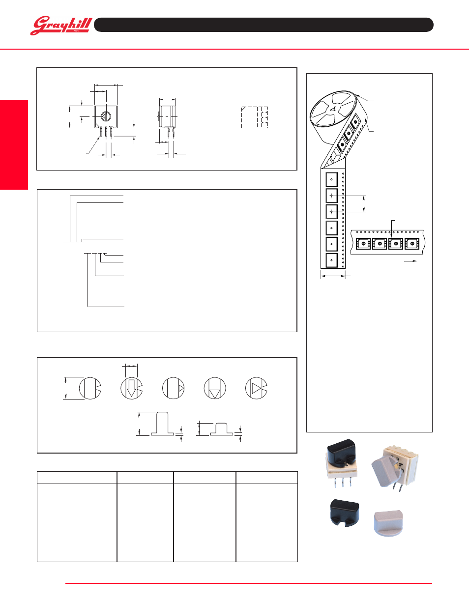
Tape and Reel packaging:
Series 94H
available from your local grayhill distributor.
For prices and discounts, contact a local Sales
Office, an authorized Distributor or Grayhill.
0
4
12
3
7
6
5
0
4
12
3
7
6
5
0
4
12
3
7
6
5
0
4
1
2
3
7
6
5
0
4
1
2
3
7
6
5
0
4
1
2
3
7
6
5
0
4
1
2
3
7
6
5
13 INCH
DIAMETER REEL
DIRECTION
OF FEED
16mm
24mm
CONDUCTIVE
PLASTIC EMBOSSED
TAPE
PIN #1
CHAMFER
Meets requirements of EIA 481-2.
Each reel contains the following number
of switches with a 15.35 inch (390 mm)
minimum leader and a 6.30 inch (160 mm)
minimum trailer.
94HA style
750 sw/reel
94HB style
150 sw/reel
94HC style
200 sw/reel
94HE style
300 sw/reel
94HF style
750 sw/reel
knob Style and Height
knob color
arrow color
part number
1A
Gray
N/A
947706-001
5A
Gray
Black
947706-005
1B
Black
N/A
947705-001
1B
Gray
N/A
947705-012
2B
Gray
White
947705-004
3B
Gray
Black
947705-017
4B
Gray
Black
947705-018
1B
Natural
N/A
947705-009
4B
Black
White
947705-010
5B
Gray
Black
947705-019
ORdeRing infORmaTiOn:
Series 94 High Temperature knobs*
*Ordered as a separate item. B = Standard (Natural), C = Complementary (Contrasting Color).
ORdeRing infORmaTiOn: Series 94H
Series
actuator Style: A = Flush, Figure 1
B = .270, Figure 3 (see page B-21)
C = .170, Figure 3 (see page B-21)
E = .090, Figure 3 (see page B-21)
F = Flush, Figure 2
code: B = Standard (Natural),
94HaB10WRT
C = Complementary (Contrasting Color)
RoHS compliant
packaging: R = Tape and Reel, (Surface Mount Only)
Blank = Tube*
Terminal Style: RA = Right Angle, Thru-Hole
J = J-Lead
W = Surface Mount
Blank = Thru-Hole
number of positions: 08 = Octal, 8 Position
10 = BCD, 10 Position
16 = Hex, 16 Position
* 27 Pieces per tube for surface mount and thru-hole, 24 pieces per tube for right angle switches.
SeRieS 94 High Temperature knobs:
for Shaft extensions
.370
(9,40)
.190
(4,83)
.395
(10,0)
.040
(1,02)
.210
(5,33)
.040
(1,02)
1
2
3
4
5
A
B
Slotted knobs show switch
markings. Contact Grayhill
for other knob material/
marking color combinations
and geometrics.
* Use only with Actuator Type B or C
Right angle Thru-Hole
dimenSiOnS
in inches (and millimeters)
4
C
1
2
C
8
0
1
2 3
4
5
67
.430 (10,92)
.210 (5,33)
.190
(4,83)
.400
(10,16)
PIN #1
.100 ± .005 TYP.
(2,54 ± 0,13)
.145
(3,68)
.282 (7,16)
.156
(3,96)
4
C
1
2
C
8
8
C
2
1
C
4
01
2
3 4 5 6
7
.190 (4,83)
2 PLACES
PIN #1
.390
(9,91)
.380 (9,65)
.500
(12,7)
.025 (0,64)
.060
(1,52)
TYP.
.100 ± .005
(2,54 ± 0,13)
TYP.
.020 +.004/-.002
(0,51 + 0,10/0,05)
TERMINALS ARE
.020 +.004/-.002
(0,51 +0,10/0,05)
WIDE BY .012 ±.002
(0,31 ±0,05) THICK
.038 DIA. HOLE SIZE
RECOMMENDED
PC board layout
as viewed from the
top of the switch
PC board layout
as viewed from the
top of the switch
Solder pad layout
as viewed from the
top of the switch
01
2
3 4 5 6
7
.390
(9,91)
.040 ± .005
(1,02 ± 0,13)
.100 ± .005 TYP.
(2,54 ± 0,13)
.190 (4,83)
2 PLACES
CORNER
CLOSEST
TO PIN #1
.380 (9,65)
.146 (3,71)
.300 (7,62) TYP.
TERMINALS ARE
.020 ± .002
(0,51 ± 0,05)
WIDE BY
.012 ±.002
(0,31 ± 0,05)
THICK
.225 (5,72)
.225 (5,72)