Grayhill DIP Switches: Thru-Hole 79 Series User Manual
Thru-hole dip switches, Series 79a, Series 79c
Grayhill, Inc. • 561 Hillgrove Avenue • LaGrange, Illinois 60525-5997 • USA • Phone: 708-354-1040 • Fax: 708-354-2820 • www.grayhill.com
Thru-Hole DIP Switches
DIP Switches
SerieS 79A
Linear Action Circuit Selector
SerieS 79C
Linear Action Tap
FeATureS
• Single-Setting Programming
• Isolated or Bussed Circuits
• 10 Positions
• 125 mA, 6 Vdc, 2000 Cycles
• RoHS Compliant
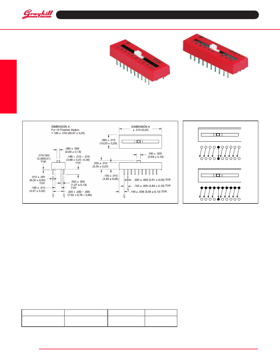
DiMeNSiONS
in inches (and millimeters)
Circuit Selector
Each position is a single isolated circuit, which
connects the two terminals across the switch
package. The movable contact is non-shorting.
Tap Switch
All contacts on one side of the switch are
internally bussed for a common pole. Any terminal
on that side may be used as a common, the
others may be clipped. The movable contact is
non-shorting.
CirCuiTry
SpeCiFiCATiONS
electrical ratings
Make-and-break Current rating: 2,000 cycles
at 10 mA, 50 mVdc; 2,000 cycles at 125 mA, 6
Vdc; 2,000 cycles at 50 mA, 30 Vdc.
Contact resistance: (measured at 10 mA, 50
mVdc) Coded Switches: 60 mohms maximum
initially. Other Switches: 50 mohms maximum
initially. After LIfe: 100 mohms maximum
insulation resistance (at 100 Vdc):
Between adjacent isolated contacts:
Initial:5,000 Mohms; 1,000 Mohms minimum
after life. Across open contacts: Initial: 5,000
Mohms; 1,000 Mohms minimum after life.
Dielectric Strength: Between adjacent isolated
contacts and also across open contacts. Initially:
750 Vac: 500 Vac after life
Contact Carry rating: 2 Amps with a maximum
contact temperature rise of 20°C
Mechanical ratings
Mechanical Life: 4,000 cycles maximum. Note:
a cycle is one complete operation, back and forth
through all switch positions.
Vibration resistance: 10 to 2,000 Hz at 15G
or 0.060" double amplitude, per MIL-STD-202F
per MIL-5-83504; Method 213, Condition A. No
damage and no contact openings exceeding 10
mS (Method 204, Test Condition B).
Shock resistance: 509, 11 mS, half sine; no
damage and no openings exceeding 10 mS
(Method 213, Test Condition A).
environmental rating
Operating Temperature: -40°C to +85°C
Storage Temperature: -55°C to +85°C
Moisture resistance: 240 hours with
temperature cycling and polarization, per MIL-
STD-202F, Method 305
Materials and Finishes
Nonconductive parts: Plastic UL94V-O
Shorting Arm: Phosphor bronze, gold plate
over nickel plate
Base Contacts: Copper alloy, gold plate over
nickel plate
Terminals: Copper alloy, matte tin plated over
nickel barrier.
potting Material: Epoxy
Tape and Seal packaging
Seal Strength: Per MIL-STD-202, Method 112.
30 seconds at 125° hot Fluorocarbon
Solderability: Per MIL-STD-202, Method 208.
Tape Seal: Polyester film
Available from your local Grayhill
Distributor.
For prices and discounts, contact a local
Sales Office, an authorized local Distributor
or Grayhill.
Circuit Selector
Tap Switch
1 2 3 4 5 6 7 8 9 10
1 2 3 4 5 6 7 8 9 10
Number of positions
Type of Circuit Code
Number per Tube
part Number*
10
Circuit Selector
9
79A10T
10
Single Pole
9
79C10T
OrDeriNG iNFOrMATiON
*A top tape seal is required for switches that are machine soldered or heavily cleaned after hand
soldering. To order top seal versions, add "S" before the "T" in the Grayhill part number.