Grayhill Mechanical Rotary Encoders 71 Series User Manual
Mechanical encoders, Series 71, Dimensions
Optical and Mechanical
Encoders
Grayhill, Inc. • 561 Hillgrove Avenue • LaGrange, Illinois 60525-5997 • USA • Phone: 708-354-1040 • Fax: 708-354-2820 • www.grayhill.com
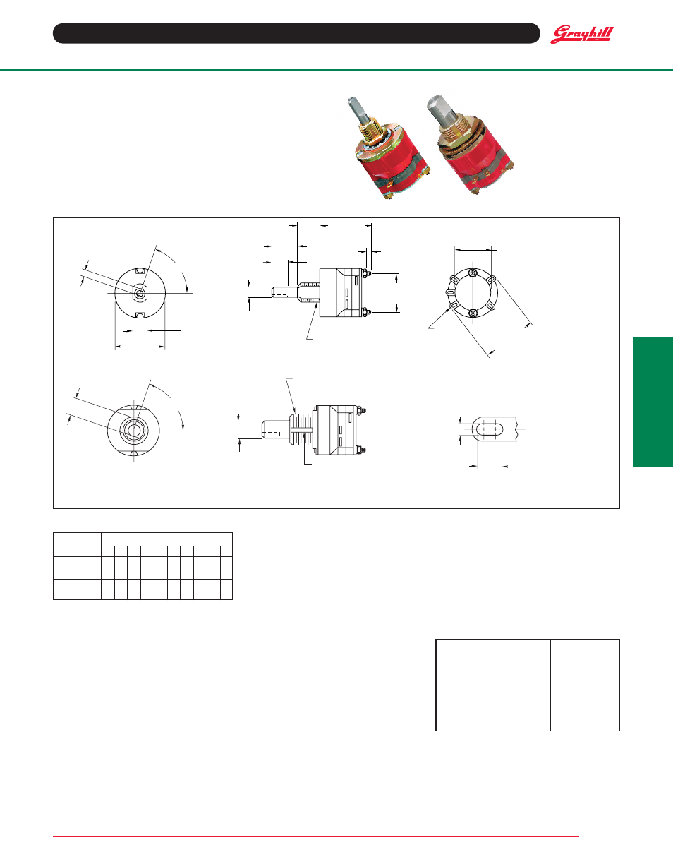
Mechanical Encoders
0.125"
Diameter
Shaft
All dimensions and rear view not shown for
the .250" diameter shaft type are the same
as the .125" diameter shaft type.
DIMENSIONS
in inches (and millimeters)
Rear mounting
plate stamping
indicates CODED
output terminals,
not decimal posi-
tions.
Grayhill part number and date code marked on label. Customer part number marked on request.
CODE aND TruTh TablE
Output
Decimal Position
Terminal 0 1 2 3 4 5 6 7 8 9
1
l l l l l
2
l l
l l
4
l l l l
8
l l
l
Indicates contact is made to the common.
SPECIfICaTIONS
Electrical rating
rated: To make and break 125 mA at 30 Vdc
resistive at standard conditions
life Expectancy: 25,000 cycles at rated load;
50,000 cycles mechanical. For ratings at different
loads and conditions, contact Grayhill.
Contact resistance: 100 milliohms maximum
(50 milliohms initially)
Insulation resistance: As measured between
mutually insulated parts
Initially:
50,000 megohms minimum
After Life: 10,000 megohms minimum
Voltage breakdown: 500 Vac between mutually
insulated parts
Carry Current: These switches will carry 3
amperes with a maximum contact temperature
rise of 20°C.
OPTIONS
Shaft and Panel Seal
Shaft is sealed by o-ring inside the bushing;
panel is sealed by o-ring at the base of the
bushing. Seals do not alter dimensions as shown
in the drawing when switch is mounted. Panel
seal is silicone rubber. Shaft seal is an o-ring
per MIL-P-5516B. Shaft and panel seal is not
available on adjustable stop switch.
additional Characteristics
rotational Torque: 8 to 16 oz-in.
Contacts: Non-shorting wiping contacts
Shaft flat Orientation: As shown in the
drawing, switch would provide a decimal 1
output.
Materials and finishes
base: Diallyl per MIL-M-14
rotor Mounting Plate: Thermoplastic.
rotor Contact: Phosphor Bronze, gold-plated
30 microinches minimum
Terminals: Brass, gold plate (20 microinches
min) over silver plate (300 microinches min)
additional Materials: Other switch materials
and finishes are the same as listed for the
standard switch.
adjustable Stop Switches
Adjustable stop switch lets you limit the number of
positions. Remove and relocate pins in the front
plate. A sticker holds the pins in place. With the
exception of holes in the front plate, all dimensions,
ratings, and characteristics are the same as the
other Series 71 coded switches. For diagrams,
see Standard Switch.
available from your local Grayhill
Distributor.
For prices and discounts, contact a local
Sales Office, an authorized local Distributor or
Grayhill.
OrDErING INfOrMaTION
Shaft Diameter
Part
and Description
Number
1/8" Continuous Rotation
71aY23401
1/8" Cont. Rot., Sealed
71aY23402
1/4" Continuous Rotation
71bY23403
1/4" Cont. Rot., Sealed
71bY23404
1/8" Adjustable Stops
71aD36-3118
1/4" Adjustable Stops
71bD36-3119
SErIES 71
binary Code
fEaTurES
•
1
/
4
" or
1
/
8
" Shaft Diameters
• 25,000 Cycles at 125 mA
• Optional Seal Versions
• Adjustable Stop Versions
OF
BUSHING
FLATS
C
L
.094 – .010
(2,39 – 0,25)
OF SHAFT
FLAT
C
L
.203 – .005
(5,16 – 0,13)
.687 – .015
(17,45 – 0,38)
DIA.
.562 – .015
(14,27 – 0,38)
1/4 32-UNEF-2A
THREAD
.125 + .001/ .002
(3,18 + 0,03/ 0,05)
.031 (0,79)
REF.
.761 – .046
(19,33 – 1,17)
.312 – .020
(7,92 – 0,51)
.375 – .020
(9,53 – 0,51)
.250 – .020
(6,35 – 0,51)
.500 – .015
(12,7 – 0,38)
DIA.
SEE
DETAIL A
.750 – .020
(19,05 – 0,51)
OVER TERMINALS
GRAYHILL
81073
8
1
4
C
2
72
SHAFT IS
SHOWN
IN POSITION 1
OF
BUSHING
KEYWAY
C
L
.219 ± .004
(5,56 ± 0,10)
OF SHAFT
FLAT
C
L
72°
.250 + .001/ –.002
(6,35 + 0,03/ –0,05)
3/8 32-UNEF-2A
THREAD
BUSHING KEYWAY
.066 ± .002 (1,68 ± 0,05) WIDE
BY .036 ± .003 (0,91 ± 0,08)
FROM A .375 (9,53) DIAMETER
Detail A
.068 ± .005
(1,73 ± 0,13)
.034 ± .003
(0,86 ± 0,08)
SHAFT IS
SHOWN
IN POSITION 1
0.250"
Diameter
Shaft