Optical encoders, Specifications, Joystick operation – Grayhill Joysticks/NavCoders 60AR Series User Manual
Page 2: Encoder waveform and truth table, Specifications are subject to change, Joystick truth table, Encoder waveform (c.w. rotation) switch schematic, Encoder truth table (c.w. rotation), Environmental specifications, Joystick electrical & mechanical specifications
Optical and Mechanical
Encoders
Grayhill, Inc. • 561 Hillgrove Avenue • LaGrange, Illinois 60525-5997 • USA • Phone: 708-354-1040 • Fax: 708-354-2820 • www.grayhill.com
Optical Encoders
JOYSTiCK OPerATiON +
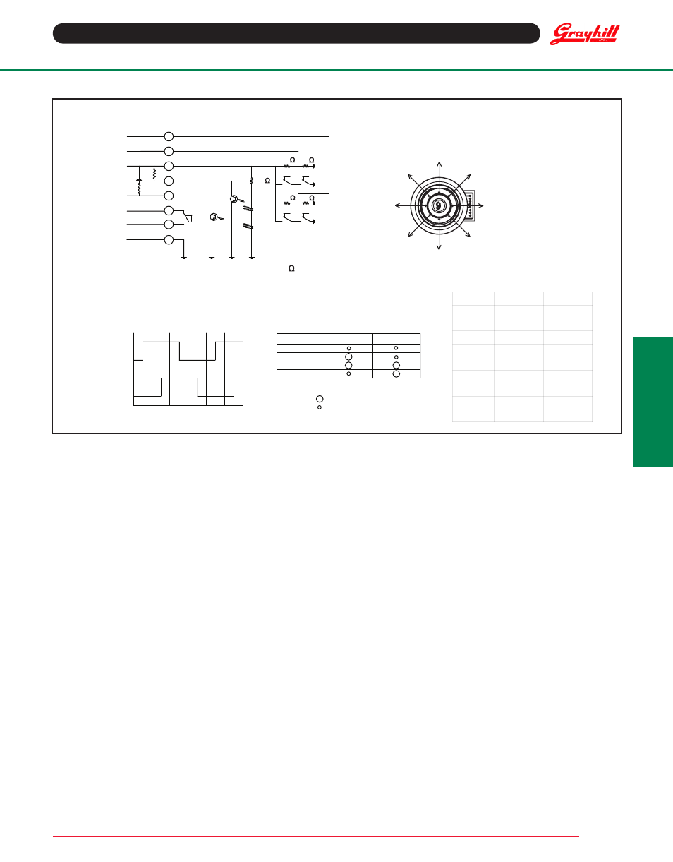
eNCODer WAVeFOrM AND TrUTH TABLe
Standard Quadrature 2-Bit Code
Specifications are subject to change
POSITION
X OUTPUT
Y OUTPUT
1
2.5
HIGH
2
HIGH
HIGH
3
HIGH
2.5
4
HIGH
LOW
5
2.5
LOW
6
LOW
LOW
7
LOW
2.5
8
LOW
HIGH
9
2.5
2.5
JOYSTICK
TRUTH TABLE
HIGH
LOW
HIGH
LOW
OUTPUT A
OUTPUT B
POS.
#1
POS.
#2
POS.
#3
POS.
#4
POS.
#5
POS.
#6
ENCODER WAVEFORM
(C.W. ROTATION)
SWITCH SCHEMATIC
1
7
8
OUTPUT A
OUTPUT B
NORMALLY OPEN
PUSHBUTTON
SWITCH
GROUND
R*
R*
5
6
4
3
POWER +5.0V
JOYSTICK
Y DIRECTION
JOYSTICK
X DIRECTION
2
10k
10k
10k
10k
180
EXTERNAL PULL-UP RESISTORS REQUIRED FOR OPERATION (2.2k
).
*
JOYSTICK POSITION DIAGRAM
* INDICATES DIRECTION OF
D-FLAT ON BUSHING
5
1*
8
7
6
4
3
2
POSITION
OUTPUT A
OUTPUT B
#1
#2
#3
#4
INDICATES LOGIC-HIGH
INDICATES LOGIC-LOW
CODE REPEATS EVERY FOUR POSITIONS
ENCODER
TRUTH TABLE
(C.W. ROTATION)
SPeCiFiCATiONS
environmental Specifications
Operating Temperature range: -40
o
C to 85
o
C
Storage Temperature range: -40
o
C to 100
o
C
Humidity: 96 hours at 90-95% humidity at 40
o
C
Mechanical Vibration: Harmonic motion with amplitude of 15g, within
a varied 10 to 2000 Hz frequency for 12 hours
Mechanical shock:
Test 1: 100g for 6Ms half sine wave with velocity change of 12.3 ft/s.
Test 2: 100g for 6 Ms sawtooth wave with velocity change of 9.7 ft/s.
Shaft and panel Seal: IP67, 1 meter submersion for 30 minutes
Joystick electrical & Mechanical Specifications
Supply Current: 5 Ma, maxium
Output Code: 2-bit
Logic Output Characteristics: Neutral Position: 2.5±0.5 Vdc,
High-state Position: >4.5 Vdc, Low-state Position: <0.5 Vdc
Mechanical Life (Joystick): 500k actuations, minimum
in each direction
Actuation Force (Joystick): 1500±300g (X&Y directions only)
Angle of Throw: 3.5
o
+2/1
o
(X&Y directions only, at electrical contact)
Pushbutton electrical & Mechanical Specifications
rating: 10 Ma at 5 Vdc, resistive
Contact resistance: Less than 10 Ω
Contact Bounce: <4 Ms make, <10 Ms break
Mechanical Life (Pushbutton): 1 million actuations, minimum
Actuation Force (Pushbutton): 1600±400g
Pushbutton Travel: .015±.005 in
rotary electrical & Mechanical Specifications
Operating Voltage: 5.00±25 Vdc
Supply Current: 20 Ma, maximum at 5 Vdc
Minimum Sink Current: 2.0 Ma for 5 Vdc
Output: Open collector phototransister, external pull-up resistors
are required
Output Code: 2-bit quadrature, channel "A" leads channel "B"
by 90
o
electrically during clockwise rotation of the shaft
Logic Output Characteristics: Logic-high shall be no less than
3.5 Vdc, Logic-low shall be no greater than 1.0 Vdc
Optical rise Time: 30 µs, maximum
Optical Fall Time: 30 µs, maximum
Mechanical Life (rotational): 1 million cycles, minimum
(1 cycle is a rotation through all positions and a full return)
Average rotational Torque: 8.0±30% in-oz, initial
Shaft Push-out Force: 60 lbs, minimum before failure
Shaft Side-load Force: 25 lbs, minimum before failure
Terminal Strength: 15 lbs pull-out force, minimum for cable
or header termination
Solderability: 95% free of pin holes or voids
Maximum rotational Speed: 100 Rpm
Mounting Torque: 15 in-lbs maximum