Butt contact pushbutton switches, Dimensions, Accessories – Grayhill Pushbutton switches: Butt Contact 39 PC Mount Series User Manual
Page 2: Ordering information, Specifications, Circuitry, Right angle, spst–normally open, Rating criteria, Materials and finishes, Spst–normally open, with panel and button seal
Pushbutton Switches
Grayhill, Inc. • 561 Hillgrove Avenue • LaGrange, Illinois 60525-5997 • USA • Phone: 708-354-1040 • Fax: 708-354-2820 • www.grayhill.com
Butt Contact Pushbutton Switches
Action
Actuating
Force (oz.)
Total
Travel
.035 ± .015
(0,89 ± 0,38)
Rating at
28 Vdc
Resistive
Operations
at Rated
Load
Button
Color
150 mA
1,000,000
39-501 RED
Red
39-501 BLK
Black
39-503 RED
Red
39-503 BLK
Black
Mounting Footprint
39-501*
39-503*
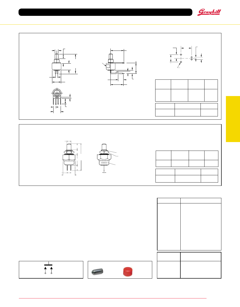
Right Angle, SPST–Normally Open
DIMENSIONS
in inches (and millimeters)
*Complete
Part
Number
Momentary
4
ACCESSORIES
30B1012-5
30B1012-8
30B1012-9
Part No.
Type & Button Color
39-401 RED
N.O., Red
39-401 BLK
N.O., Black
39-405 RED
N.O., No Nut, Red
39-405 BLK
N.O., No Nut, Black
39-424 RED
N.O., Overtravel, Red
39-424 BLK
N.O., Overtravel, Black
39-501 RED
N.O., Right Angle, Red
39-501 BLK
N.O., Right Angle, Black
39-503 RED
39-501 Red & Cap Seal
39-503 BLK
39-501 Blk & Cap Seal
39-138 RED
39-351 PC Mount & Seal
39-138 BLK
39-351 PC Mount & Seal
ORDERING INFORMATION
Accessory
Part Number
Description
30B1012-5
Red Accessory Cap
30B1012-8
White Accessory Cap
30B1012-9
Black Accessory Cap
SHH1699
Cap Seal Only, Black
SPECIFICATIONS
Rating Criteria
Contact Resistance: 25 milliohms maximum
on a new switch
Voltage Breakdown: 1,000 Vac between
mutually insulated parts
Insulation Resistance: 1,000 megohms
minimum
Operating Temperature: -40°C to +85°C
* Note: Solder process temperatures should
not expose main switch body to temperatures
higher than 270F. (132C). Reflow soldering is
not recommended. Contact Grayhill for more
specific details.
Available from your local Grayhill Distributor. For prices and discounts, contact a local Sales Office, an authorized Distributor or Grayhill.
Protective cap
(included with 39-503
RED and 39-503 BLK)
seals switch during
wave soldering.
+ 4
– 2
CIRCUITRY
HOLES FOR
.020 (0,51)
SQUARE PINS (4)
.100
(2,54)
.200
(5,08)
.100 (2,54)
.300
(7,62)
.050 (1,27)
.110 (2,79)
± .010 (0,25) DIA.
.175 +.025/ –.020
(4,45 +0,64/ – 0,51)
A = .125 ± .010
(3,18 ± 0,25)
.600
(15,24)
REF.
.100 (2,54) REF.
.250 + .010/ –.005
(6,35 + 0,25/ – 0,13) DIA.
A
B
C
.315 ± .010
(8,00 ± 0,25)
.300 ± .005
(7,62 ± 0,13)
.089
(2,26)
MIN.
C = .060 ± .005
(1,52 ± 0,13)
.075 ± .010
(1,91 ± 0,25)
.300 (7,62)
REF.
.050 ± .010
(1,27 ± 0,25)
.140 ± .015
(3,56 ± 0,38)
.200 ± .005
(5,08 ± 0,13)
.050 (1,27)
REF.
B = .215 ± .015
(5,46 ± 0,38)
E.I.A.
DATE
CODE
LABEL*
*Label increases
nominal diameter
to .255 (6,48)
SPST–N.O.
Materials and Finishes
Bushing/Housing: Aluminum, clear anodized
for 39-138; Brass, tin zinc for all others
Standoff: (39-501 and 39-503) Brass, tin plated
over nickel
Base and Button: Thermoplastic
Shorting Bar: Brass, gold-plated over nickel
plate for 39-501and 39-503; fine silver, gold-
plated for others
Terminals: Fine silver, gold-plated for 39-138;
Brass, gold-plated over nickel for all others
Spring: Tinned music wire
Mounting Nut: (39-401 and 39-424) Brass,
zinc trivalent chromate-plated
.110 ± .005 DIA.
(2,79 ± 0,13)
.312±.005
(7,92±0,13)
ACROSS FLATS
.110 ± .005
(2,79 ± 0,13)
.692 REF
(17,58)
A=.175+.025/-.020 (4,45+0,64/-0,51)
B=.125±.010 (3,18±0,25)
C=.250±.015 (6,35±0,38)
D=.135±.005 (3,43±0,13)
A
B
C
D
#8-40 UNS-2A
THREAD
HEX MTG. NUT
.0625 (1,59) THICK
.218 (5,54) ACROSS FLATS
E.I.A. DATE CODE
.020±.002
(,508±,051)
SQUARE TYP
SPST–Normally Open, with Panel and Button Seal
39-138*
Rating at
115 Vac
Resistive
Operations
at Rated
Load
Button
Color
39-138 RED
Red
39-138 BLK
Black
½ Amp
250,000
*Complete
Part
Number
Action
Actuating
Force (oz.)
Total
Travel
.035 ± .015
(0,89 ± 0,38)
Momentary
16 ± 8
SHH1699