Wiping contact pushbutton switches, Dimensions, Accessory circuitry – Grayhill Pushbutton switches: Wiping Contacts 46 Series User Manual
Page 3: Specifications, Standard options, Ordering information
Grayhill, Inc. • 561 Hillgrove Avenue • LaGrange, Illinois 60525-5997 • USA • Phone: 708-354-1040 • Fax: 708-354-2820 • www.grayhill.com
Pushbutton Switches
Wiping Contact Pushbutton Switches
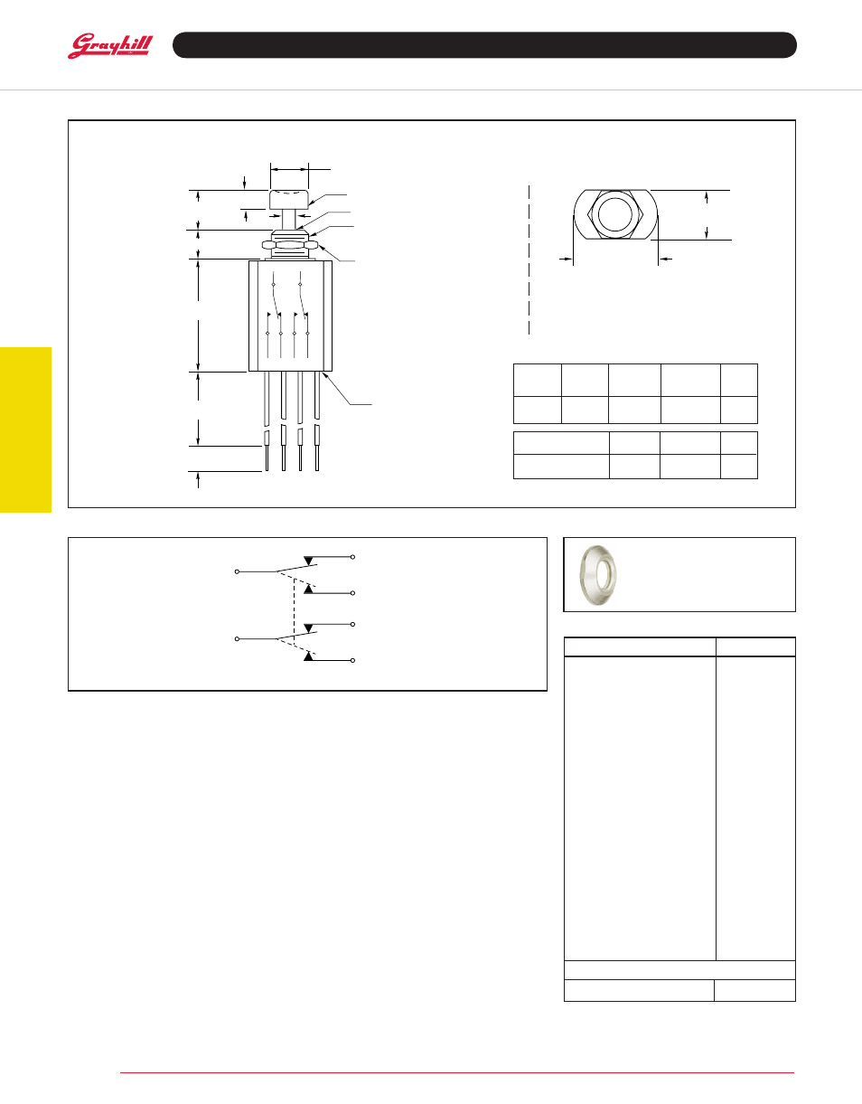
diMenSiOnS
in inches (and millimeters)
aCCeSSOry
CirCuitry
46-260* (BBM)
environmentally Sealed
double Pole/double throw
Mtg.
Hole
Bottoming
Force (oz.)
total
travel
46-260 RED
Red
46-260 BLK
Black
Operations
at rated
Load
rating at
220 Vac
resistive
Cap
Color
Momentary
Approx. 45
1
/
4
Amp
1
/
8
Amp 250,000
action
description
Part no.
SPDT, BBM, Red Button
46-101 red
SPDT, BBM, Black Button
46-101 BLK
SPDT, BBM, Red Cap
46-102 red
SPDT, BBM, Black Cap
46-102 BLK
SPDT, MBB, Red Button
46-110 red
SPDT, MBB, Black Button
46-110 BLK
SPDT, MBB, Red Cap
46-111 red
SPDT, MBB, Black Cap
46-111 BLK
SPDT, BBM, Red Cap
46-150 red
SPDT, BBM, Black Cap
46-150 BLK
SPDT, MBB, Red Cap
46-151 red
SPDT, MBB, Black Cap
46-151 BLK
DPDT, BBM, Red Cap
46-200 red
DPDT, BBM, Black Cap
46-200 BLK
DPDT, MBB, Red Cap
46-201 red
DPDT, MBB, Black Cap
46-201 BLK
DPDT, BBM, Red Cap
46-270 red
DPDT, BBM, Black Cap
46-270 BLK
DPDT, MBB, Red Cap
46-271 red
DPDT, MBB, Black Cap
46-271 BLK
DPDT, BBM, Sealed, Red
46-260 red
DPDT, BBM, Sealed, Black
46-260 BLK
aCCeSSOry
Decorative Nut
30C1023-1
rating at
115 Vac
resistive
decorative Mounting nut
Part No. 30C1023-1
Fits .250" (6,35) Bushing
.180 (4,57)
25/64"
Min.
(9,92)
*Complete
Part
number
SPeCiFiCatiOnS
rating Criteria
Contact resistance: Less than 25 milliohms
at the switch initially. Less than 4 milliohms/
inch of wire.
Voltage Breakdown: 1,000 Vac between
mutually insulated parts
insulation resistance: 1,000 megohms
minimum
Materials and Finishes
Cover, Bushing, Mounting nut: Brass,
tin zinc
Shorting Bar: Phosphor bronze, silver-plated.
terminals: Phosphor bronze, silver contact
surface. Terminal ends are tin/silver
Base or Potting Shell: Phenolic per MlL-M-
14, type CFG
Spring: Tinned music wire
Button Cap: Polyethylene
Button: Polyphenylene sulfide (PPS) for 46-200
and 46-201. Polycarbonate for all other unsealed
versions. Aluminum for all sealed versions.
O-ring Seal: Nitrile per MIL-P-5516, class B
Seal adapter and Hex nut (46-260): Brass,
zinc trivalent chromate-plated
Wire Leads (46-260): Per MIL-W-16878 type
E. #26 AWG, insulated teflon, copper stranded
wire
Operating Features
Break-Before-Make: Rest position to N.C. break
.020" (0,51) minimum. Rest position to N.O. Make
.140" (3,35) maximum.
Make-Before-Break: Rest position to N.O. make
.065" ± .015 (1,65 ± 0,38). Rest position to N.C.
break .130" ± .015 (3,30 ± 0,38).
Operating temperature: -40°C to +85°C
Standard OPtiOnS
Epoxy sealed terminals and wire leads
Decorative mountings
OrderinG inFOrMatiOn
.281 – .010 (7,14 – 0,25)
.390 – .010
(9,90 – 0,25)
.641 – .005
(16,28 – 0,13)
.812 – .005
(20,62 – 0,13)
DIAMETER
.375 – .010
(9,53 – 0,25) DIA.
SNAP ON BUTTON CAP
R
O
Y
BR
G
BL
A
B
.250 – .010
(6,35 – 0,25)
3/8-32 UNEF-2A
THREAD TO .060 (15,24) MAX.
FROM SHOULDER
O-RING SEALED
HEX MOUNTING NUT
.562 (14,2) ACROSS FLATS
.094 (2,40) THICK
SWITCH AND
WIRE LEADS
ENCAPSULATED
A = 1.14 (29,0)
MAX.
B = 22.00 (558,8)
MAX.
C = .187 – .010
(4,75 – 0,25)
D = .125 – .005
(3,18 – 0,13)
C
D
dPdt BBM
n.C.
n.O.
C1
n.C.
n.O.
C2