Optical encoders, Specifications, Ordering information – Grayhill Human Interface Optical Encoders 63R Series User Manual
Page 2
Optical and Mechanical
Encoders
Grayhill, Inc. • 561 Hillgrove Avenue • LaGrange, Illinois 60525-5997 • USA • Phone: 708-354-1040 • Fax: 708-354-2820 • www.grayhill.com
Optical Encoders
available from your local Grayhill Distributor. For prices and discounts, contact a local Sales Office, an authorized local Distributor or Grayhill.
sPeCiFiCations
electrical ratings
operating voltage: 5 ±.25 Vdc
supply Current: 30 mA maximum at 5 Vdc
Logic output Characteristics:
Output Type: Open collector with integrated
Schmitt Trigger and 10 KW pull-up resistor
Maximum Sink Current:
16 mA at .40 volts
Power Consumption: 150 mW maximum
optical rise time: 500 nS typical
optical Fall time: 14 nS typical
mechanical ratings
mechanical Life: 300 million revolutions
time Life: Guaranteed for 10 years of
continuous operation (calculated from emitter
degradation data)
mounting torque: 20 in-lbs maximum
terminal strength: 5 lbs terminal pull-out
force minimum
solderability: 95% free of pin holes and voids
externally applied shaft Force:
Axial:15 lbs maximum; Radial:15 lbs
maximum
operating torque: 0.5 in-oz maximum (no
detents) for unsealed versions
environmental ratings
operating temperature range: -40°C to 85°C
storage temperature range: -55°C to 100°C
relative Humidity: 90-95% at 40°C for 96 hours
vibration resistance: Harmonic motion with
amplitude of 15g, within a varied 10 to 2000
Hz frequency for 12 hours per MIL-STD-202,
Method 204
shock resistance: Test 1: 100g for 6 mS, half-
sine wave with velocity change of 12.3 ft/s. Test
2: 100g for 6 mS, sawtooth wave with velocity
change of 9.7 ft/s.
materials and Finishes
Bushing: Zinc diecast
Housing: Zytel FR-50
shaft: Stainless steel insert molded into nylon
rotor support
Code rotor and aperture: Chemically
etched stainless steel/electroformed nickel
Printed Circuit Board: NEMA Grade FR-4.
Five microinches minimum gold over 100
microinches minimum nickel over copper
optical Barrier: Polyphenylene sulfide, 94 V-0
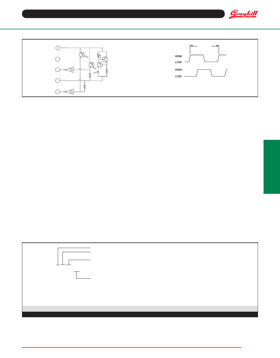
CirCuitry anD WaveForm: standard Quadrature 2-Bit Code
Backplate: Polyester
Header: Phosphor bronze, 200 microinches
tin over 50 microinches nickel (pin version only)
infrared emitter: Gallium aluminum arsenide
Photo iC: Planar silicon
retaining ring: Stainless steel
Cable: 26 AWG, stranded/tinned wire, PVC
coated on .100 (2,54) centers (cable version only)
Connector: Glass-filled PCT, UL94V-0
Bearing subassembly
Bearing: NSK ABEC 5 (stainless steel)
Preload Collar: 303 stainless steel
spacer: 303 stainless steel
Bellville spring: spring steel (stainless)
1 CYCLE
OUTPUT
A
OUTPUT
B
CHANNEL A LEADS CHANNEL B BY
90˚ ± 45˚ IN ALL ROTATIONS FOR
CLOCKWISE ROTATION OF SHAFT.
1
2
3
5
4
10 K
Ω
10 K
Ω
PIN #
GROUND
NO CONTACT
OUTPUT A
POWER 5V
OUTPUT B
orDerinG inFormation
series
style: R = Standard, 5-pin, high resolution
RS = Sealed, 5-pin, high resolution
Cycles: per channel per revolution = 25, 32, 50, 64, 100, 128, 256
63rs256–060
termination:
Blank (no dash or numbers): pins as described in drawing.
Cable termination: 060 = 6.0in. Cable is terminated with Molex Connnector P/N 14-56-3056