Optical encoders, Specifications, Options – Grayhill Human Interface Optical Encoders 62R Series User Manual
Page 2: Circuitry, truth table, and waveform, Ordering information
Optical and Mechanical
Encoders
Grayhill, Inc. • 561 Hillgrove Avenue • LaGrange, Illinois 60525-5997 • USA • Phone: 708-354-1040 • Fax: 708-354-2820 • www.grayhill.com
Optical Encoders
SPECIFICATIONS
Pushbutton Switch Ratings
Pushbutton Rating: 10 mA, 5 Vdc, resistive
Contact Resistance: less than 10 ohms (TTL
or CMOS compatible)
Pushbutton Life: 3 million actuations min.
Contact Bounce: less than 4 mS at make
and less than 10 mS at break
Actuation Force: 1000 ±300 grams
Pushbutton Travel: .010/.025"
Switch Ratings
Coding: 2-bit quadrature coded output
Operating Voltage: 5.0 ±.25 Vdc
Voltage Breakdown: 250 Vac between
mutually insulated parts
Supply Current: 30 mA [email protected] Vdc
(per deck)
Logic Output Characterisitics:
Logic High: 3.5 Vdc minimum
Logic Low: 1.5 Vdc maximum
Mechanical Life: 1,000,000 cycles minimum
(One cycle is a rotation through all positions
and a full return)
Minimum Sink Current: 2.0 mA
Power Consumption: 150mW max. (per
deck)
Output: open collector phototransistor
Optical Rise and Fall Times: less than 30
mS maximum
Operating Torque: 3.5 ±1.4 in-oz initially
Shaft Push Out Force: 45 lbs minimum
Mounting Torque: 15 in-lbs max.
Terminal Strength: 15 lbs cable pull-out force
min.
Operating Speed: 100 RPM max.
Environmental Ratings
Operating Temperature Range: -40°C to
85°C
Storage Temperature Range: -55°C to
100°C
Vibration Resistance: Harmonic motion with
amplitude of 15G's, within a varied 10 to 2000
Hz frequency for 12 hours
Mechanical Shock: Test 1: 100g, 6 mS, half
sine, 12.3 ft/s; Test 2: 100g, 6 mS, sawtooth,
9.7 ft/s
Humidity: 90–95% at 40°C for 96 hours
Materials and Finishes
Shaft: Aluminum
Bushing: Zinc casting
Shaft Retaining Ring: Stainless steel
Detent Spring: Stainless steel
Printed Circuit Boards: NEMA grade FR-4
gold over nickel or palladium
Terminals: Brass, tin-plated
Mounting Hardware: One brass, nickel-plated
nut and zinc-plated spring steel with clear
trivalent chromate finish lockwasher supplied
with each switch. (Nut is 0.094 inches thick by
0.433 inches across flats)
Rotor: Thermoplastic
Code Housing: Thermoplastic
Pushbutton Dome: Stainless steel
Dome Retaining Disk: Thermoplastic
Pushbutton Housing: Thermoplastic
Phototransistor: Planar Silicon NPN
Infrared Emitter: Gallium aluminum
arsenide
Pushbutton Contact: Brass, nickel-plated
Flex Cable: 28 AWG stranded, halogen-free
polyolefin insulation on .050" centers (cabled
version)
Header Pins: Phospher bronze, tin-plated
Spacer: Zinc casting
Backplate/Strain Relief: Stainless steel
Studs: Stainless steel
OPTIONS
Contact Grayhill for custom terminations, shaft
and bushing configurations, and resolutions.
Control knobs are also available.
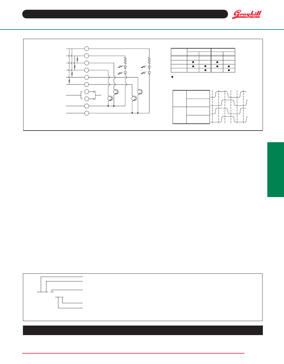
CIRCUITRY, TRUTH TABLE, AND WAVEFORM
Standard Quadrature 2-Bit Code
Series
Angle of Throw: 15 = 15° or 24 pos, 22 = 22.5° or 16 positions,
30 = 30° or 12 Positions
Pushbutton Option: 01 = w/o pushbutton, 02 = with pushbutton
62R22-01-040S
Termination: .050" centers; S = Stripped cable, C = Connector, P = Pin
Cable Length: 040 = 4.0 inches. Cable is terminated with Amp Connector P/N 215083-8.
See Amp Mateability Guide for mating connector details.
*Eliminate cable length if ordering pins. (Ex: 62R22-02-P)
ORDERING INFORMATION
Available from your local Component Grayhill Distributor. For prices and discounts, contact a local Sales Office, an authorized local
Distributor, or Grayhill.
Custom materials, styles, colors, and markings are available. Control knobs available.
POSITION
OUTPUT "A" OUTPUT "B"
1
2
3
4
INDICATES LOGIC HIGH. BLANK INDICATES
LOGIC LOW. CODE REPEATS EVERY 4 POSITIONS
7
6
5
4
3
2
DECK A OUTPUT "B"
DECK B OUTPUT "A"
DECK B OUTPUT "B"
DECK A GROUND
PUSHBUTTON N.O.
PIN #
Switch Schematic
Truth Table (CW Rotation)
LOW
LOW
HIGH
HIGH
OUTPUT "A"
OUTPUT "B"
POS.
#1
POS.
#2
POS.
#3
POS.
#4
POS.
#5
POS.
#6
Wave Form (CW Rotation)
OUTPUT "A" OUTPUT "B"
DECK A
DECK B
LOW
HIGH
LOW
HIGH
OUTPUT "A"
OUTPUT "B"
10
9
8
DECK B POWER 5V
DECK A OUTPUT "A"
DECK A
DECK B
1
DECK B GROUND
DECK A POWER 5V
R*
R*
R*
R*
* 2.2k EXTERNAL PULL-UP RESISTORS REQUIRED FOR OPERATION