Keylock rotary switches – Grayhill Keylock Switches 44L Series User Manual
Page 2
Grayhill, Inc. • 561 Hillgrove Avenue • LaGrange, Illinois 60525-5997 • USA • Phone: 708-354-1040 • Fax: 708-354-2820 • www.grayhill.com
Rotary Switches
Keylock Rotary Switches
Switch SPecificAtioNS
electrical characteristics
industrial grade Switch
Switching current and Life
The load-life values indicate the number of
cycles of operation expected for the voltage,
current and type of load. End of life is defined
using the resistance and breakdown failure
criteria listed below.
5A at
115 Vac, resistive
1A at
6 to 28 Vdc, resistive
2A at
115 Vac, inductive
cycle of operation: 360° rotation plus a
360° return
test conditions: 25°C, 68% relative humidity,
atmospheric pressure
Life expectancy:
With loads above: 25,000 cycles
Without load:
100,000 cycles
contact resistance:
End of life:
less than 20 mΩ
insulation resistance:
(Between mutually insulated parts)
Initially:
50,000 MΩ
Breakdown Voltage:
(Between mutually insulated parts)
Initially:
1,000 Vac
End of life:
500 Vac
carry current: 10A; maximum temperature
rise 20°C
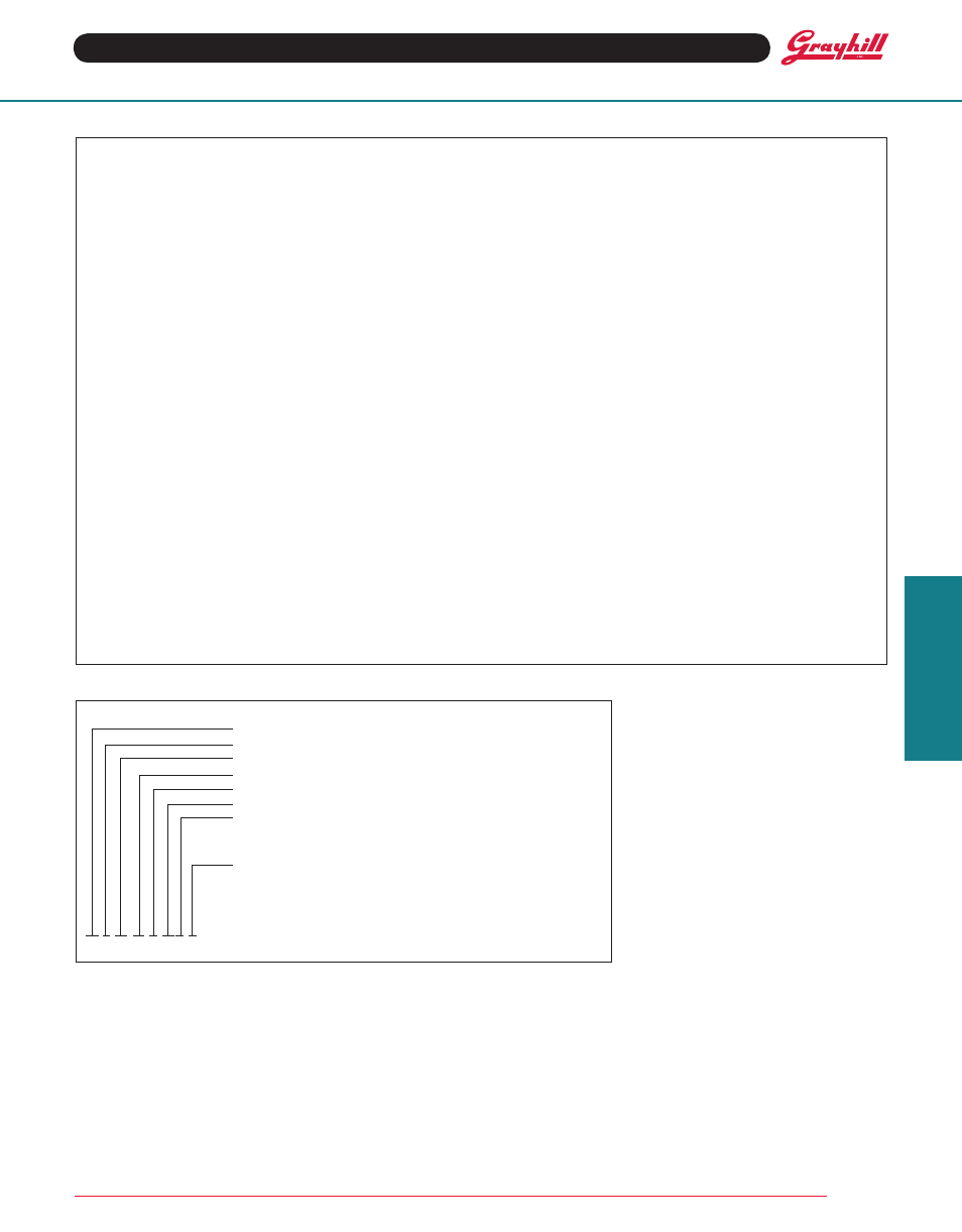
orDeriNg iNforMAtioN
44 L 45-02-1-08N-f
Series
Style Letter: L
Angle of throw: 45°
Number of Decks: 01 thru 06 (per Choices chart)
Poles per Deck: 1 thru 4 (per Choices chart)
Positions per Pole: 02 thru 08 (per Choices chart)
type of contacts:
N = Non-shorting
S = Shorting (per Choices chart)
Stop Arrangement Suffix: (needed only for 1-pole switches
with
maximum positions)
F = Fixed stop between positions 8 and 1
*Leave blank for continuous rotation
Available from your local grayhill Distributor.
For prices and discounts, contact a local
Sales Office, an authorized local Distributor or
Grayhill.
Mechanical characteristics
Switching Mode:
45°, 1 or 2 poles: Shorting or non-shorting
45°, 3 or 4 poles: Non-shorting
type of contact: Wiping contacts
contact force: greater than 150g
Number of terminals: Switches are provided
with only the number of terminals needed
Stop Strength: greater than 15 in-lbs (1.70
Nm)
Switching torque: 8-115 in-ozs (28 to 230
mNm), depending on the number of poles,
number of decks, and angle of throw
Additional characteristics
Switches of 6 or more decks have longer studs
with extra mounting nuts for recommended
double end mount
Materials and finishes: Switch
Switch Bases: Melamine per MIL–M–14, 4
Switch Bases:
Industrial Grade:
Melamine per MIL–M–14
Military: Diallyl per MIL–M–14
cover, Deck Separators, end Plate, and
rotor Mounting Plate: Phenolic per
MIL–M–14
Shaft, Shaft extension, Stop Arm, Stop
washers, rear Support Plate, cover
Plate, retaining ring, Studs, Nuts: Stain-
less steel
Detent Balls: Steel, nickel-plated
Detent Springs: Tinned music wire
rotor contact, and Stator (Base) con-
tacts: Silver alloy
common Plate, and common terminal:
Brass, 300µ inch, (7.6 µm) silver plate
Base terminals: Brass, tin plated