Multi-deck rotary switches, Specifications circuit diagrams: series 57, Rear view – Grayhill Multi-Deck Rotary Switches 59 Series User Manual
Page 3: Electrical ratings general, Electrical ratings military qualified, Materials and finishes, Additional characteristics
Grayhill, Inc. • 561 Hillgrove Avenue • LaGrange, Illinois 60525-5997 • USA • Phone: 708-354-1040 • Fax: 708-354-2820 • www.grayhill.com
Rotary Switches
Multi-Deck Rotary Switches
SPECIFICAtIONS
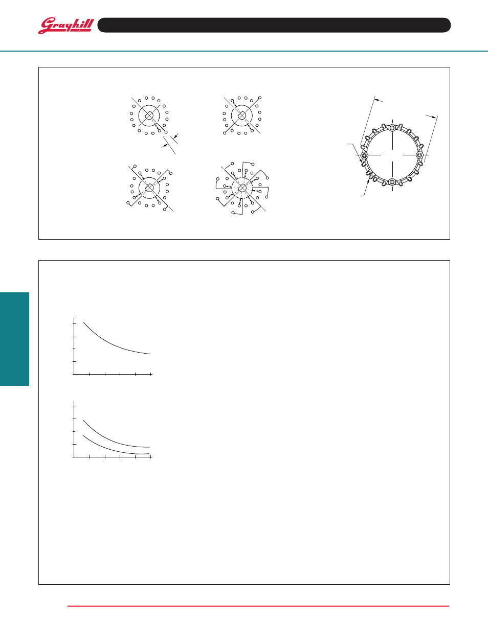
CIRCuIt DIAGRAMS: Series 57
Rear View
Switch is Viewed From Shaft End and Shown in Position No. 1.
Note: All common terminals are located above base terminals as shown.
22
1
/
2
° Angle
of throw
Note: Common location for a single pole per
deck switch. For common location on
multipole switches see circuit diagrams.
THREE OR
FIVE THRU
FOUR POLE
EIGHT POLE
ONE POLE
TWO POLE
Electrical Ratings
General
Switch rating for break before make
contacts.
Voltage: As listed in the chart.
Curve data based on test data conducted at
sea level, 25°C and relative humidity. Cycle
equals 360° rotation and 360° return. Cycling
rate is 10 cycles per minute. The curves shown
are typical load life curves for a Series 53M,
57M and 59M Rotary Switch. They show the
number of cycles of rotational life that can be
expected for the voltages, currents and types
of loads shown. Thus, with a 250 milliamperes,
30 Vdc resistive load, 10,000 cycles of life can
be expected. Life limiting or failure criteria for
these curves are:
6
2 1
15
14
8
9 10
C1
3
4
5
7
11
12
13
16
11-15°
OF BUSHING
KEyWAy
C
L
C
L OF POSITION
NO. 1
6
1
15
14
8
9 10
C1 4
5
7
11
12
13
16
C2
2
3
C
L
6
2 1
15
14
8
9
10
C1
3
4
5
7
11
12
13
16
C
L
C3
C2
C4
6
2 1
15
14
8
9 10
C1
3
4
5
7
11
12
13
16
C
L
C5
C3
C7
C2
C4
C6
C8
14
15
16
1
13
12
11
10
9
8
7
6
5
4
3
2
SEE NOTE
SEE
DETAIL
1.190 ± .015
(30,23 ± 0,38)
OVER TERMINALS
GRAyHILL
LA GRANGE
ILLINOIS
400
300
200
100
0
0
CyCLES x 1,000
5
10
25
CURRENT MILLIAMPS
VOLTAGE 115 VAC
15
20
400
300
200
100
0
0
CyCLES x 1,000
5
10
25
CURRENT MILLIAMPS
30 VDC RESISTIVE
15
20
30 VDC
INDUCTIVE
Contact Resistance: 50 milliohms maximum
(20 milliohms initially).
Insulation Resistance: 1,000 megohms
minimum between mutually insulated parts.
Voltage Breakdown: 500 Vac minimum between
mutually insulated parts. These switches will
carry 4 amperes with a maximum contact
temperature rise of 20°C. If the life limiting
characteristics are less critical than those shown
above or if elevated temperatures or reduced
pressures are involved, Grayhill can predict the
switch life for the application.
Electrical Ratings
Military Qualified
The Series 53, 57 and 59 Style HS, Rotary
Switches have been tested to make and break
the following loads as stated in MIL-DTL-3786/36:
70,000 ft. altitude for 10,000 cycles: 10mA,
28 Vdc, inductive (250 mH); 50 mA, 28 Vdc,
resistive; 20 mA, 115 Vac, resistive. Atmospheric
pressure, 125°C for 10,000 cycles: 25 mA,
28 Vdc inductive (250 mH); 75 mA, 28 Vdc,
resistive; 50 mA, 115 Vac resistive. Atmospheric
pressure, 25°C for 10,000 cycles: 75 mA,
28 Vdc, inductive (250 mH); 250 mA, 28 Vdc
resistive; 150 mA, 115 Vac, resistive. Life limiting
criteria for these loads are:
Contact Resistance: 50 milliohms maximum.
Dielectric Strength: 500 Vac (350 Vac—reduced
pressure).
Insulation Resistance: 1,000 megohms
minimum. These switches also meet MIL-DTL-
3786/36 for moisture resistance, medium and
high shock, vibration, thermal, thermal shock,
salt spray, explosion, terminal strength and
stop strength.
Materials and Finishes
Cover, Base, Spacer and Rotor Mounting
Plate: Diallyl per (MIL-M-14) ASTM-D-5948
Mounting Bushing: Brass, tin/zinc-plated.
Shaft, Stop Pins, Retaining Rings, through
Bolts, Shaft Extension, Stop Arm, thrust
Washers, Lockwashers, Nuts, Non-turn
Washer, Cover Plate and Rear Support
Plate: Stainless steel
Detent Balls: Steel, nickel-plated
Detent Springs: Tinned music wire
Rotor Contact: Silver alloy, gold-plated
.00001" minimum.
terminals and Common Plate Including
Solder Lug: Brass, gold plate .00002"
minimum over silver plate .0003" minimum.
Panel Seal: Silicone rubber.
Shaft Seal: O-ring per MIL-M-5516B.
Mounting Nut, Lock Washer: Brass, tin/zinc-
plated or stainless steel.
Additional Characteristics
Rotational torque: 20-80 in-ozs., depending
on the number of poles per deck and the
number of decks.
Contacts: Shorting or non-shorting wiping
contacts with over 100 grams of contact
force.
Shaft Flat Orientation: Flat opposite
contacting position pole #1 (See Circuit
Diagrams).
Extended Studs: Switches of 6 decks or
more have longer studs with extra stud nuts for
recommended double end mounting.
terminals: Switch is provided with full
complement of base or position terminals
regardless of the number of active positions.