Speed control schematic diagrams: (cont.), Troubleshooting – Fuelab 42402 Prodigy Fuel Pump High Power EFI In-Line User Manual
Page 4
for proper wiring and installation.
110020274-1, Rev C Page 4 of 6
SPEED CONTROL SCHEMATIC DIAGRAMS: (cont.)
recommended during long periods of
low engine fuel demand conditions to
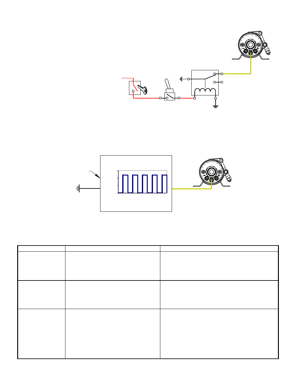
Example 4: Switch to Power Speed Changing
example. Reduced speed is
avoid fuel system heat build-up.
When the switching action is in reverse
to what can be used as shown Example 3,
such as some pressure switches, the
action can be reversed through the use
of a Single Pole Dual Throw (SPDT) relay
as shown to the right. Current draw through
this circuit is extremly low (much less
than 1 amp), so a very low current
rating for this 12 volt relay and switch
can be used. Use the diagram to the
right as a guide to properly wire this
Refer to above Example 5, for use with the Fuelab Electronic Fuel Pressure Regulator, Models 52901 and 52902,
that creates its own pulsed signal. These regulators automatically control the fuel pump, without the use of switching
means or other components such as described in examples 2 and 3. Refer to instructions for the Electronic Regulator,
TROUBLESHOOTING:
ELECTRONIC DEVICE SUCH
AS AFTERMARKET ENGINE
MANAGEMENT MODULE.
Input Signal
0
5
10
15
0
2
4
Time (sec X10
-3
)
Vo
lt
a
g
e
(
v
)
Peak Voltage shown at 12V,
typically this value is actually
peak vehicle voltage.
Square Wave Signal, at
Recommended frequency: 500-
1500Hz, (shown at 50% duty cycle)
Example 5: Variable Speed
Devices such as an aftermarket ECM can create a pulsed signal (“pulling” voltage to ground at a given frequency). This
signal has a characteristic of dwell time, which is a ratio of on-time vs. off-time (in other words, the amount of time the signal
is at vehicle voltage vs. at zero voltage). This difference in dwell time percentage will enable the fuel pump to operate at
various speeds or flow rate. A graph demonstrating an example signal created by such a device is shown below. The
example signal is at 50% duty cycle, whereas the amount time that the signal is at vehicle voltage is equal to the amount of
time at zero volts. When duty cycle is between 0-20%, the fuel pump is turned off. A duty cycle between 20%-90% will be
variable speed between minimum and maximum speeds, while duty cycles between 90% and 100% are maximum Speed.
IGNITION
SWITCH
From
+12V
Source
SPDT RELAY
(1+A RATING)
C
NO
NC
PUMP OPERATES
AT REDUCED
SPEED WITH
SWITCH POSITION
SHOWN (OPEN).
Problem Possible
Cause
Possible
Solution
Not operating or
slight “clicking”
sound when turned
on.
• Faulty fuel pump relay.
• Faulty, dirty or corroded terminals
or improperly sized wire.
• Debris from tank or plumbing
lodged inside pump.
Check voltage to fuel pump, at power terminals. If
voltage is steady and consistent (within ½ Volt of
battery) then contact Fuelab for repair. If voltage is
inconsistent as described, repair or replace electrical
components as required.
Speed of pump
changes up and
down very
noticeably and
erratically.
• Incorrect wiring of speed control
as specified in wiring Examples 1
through 5.
• Loose terminal or wiring of speed
control circuit.
Unhook speed control wiring from yellow terminal of
pump. Turn on pump; if operation is consistent, then
repair or replace components as required.
Loss of fuel
pressure or erratic
pressure pulsation
after several
minutes of
operation.
• Cavitation (vapor lock) due to
overheating or restricted inlet.
Check temperature of pump right after failure. If
pump is hot to touch (cannot leave hand on pump
due to it being too hot), then follow proper speed
control wiring example, or look for other sources of
heat such as exhaust. If pump is not hot to the touch,
check for inlet restrictions such as improperly vented
tank, kinks in the fuel line, or too small of plumbing
for application. Contact Fuelab, as pump may be
damaged due to improper operating condition.