Fuelab 42402 Prodigy Fuel Pump High Power EFI In-Line User Manual
Page 3
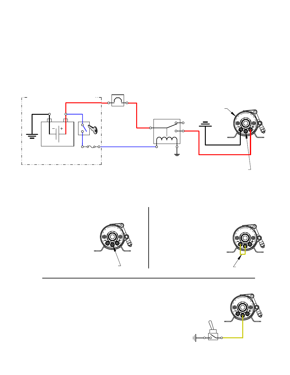
Fuelab Model:
42402-c (-sp)
FUEL PUMP
(16-20ga) Device or Circuit can be used as shown below,
for proper operation.See Speed Control Schematic Diagrams
for wiring of speed control (Yellow Lug).
PUMP OPERATES
AT MAXIMUM SPEED
WITH SWITCH POSITION
SHOWN (OPEN).
NO JUMPER WIRE
OR DEVICE
Example 3: Switch to Ground Speed Changing
110020274-1, Rev C Page 3 of 6
(Electrical components shown are not supplied with Fuel Pump)
MAIN WIRING SCHEMATIC DIAGRAM:
SPEED CONTROL SCHEMATIC DIAGRAMS:
and reduced speed.
switching between maximum
See Examples 3 and 4 for
pulsed signal may also be used to control pump speed. See examples below for a method suitable for your application.
Example 1: Continuous Maximum Speed
speed control terminal has greater than 2.5V (Approx), the mode of operation is in continuous maximum speed. A
terminal has less than 1/4V (Approx) applied to it, the mode of operation is in continuous reduced speed. When the
The speed control terminal (Yellow Center Lug) can have voltage or a signal applied to it. When the speed control
considered continuous duty.
this mode of operation is
adequate for application. Using
flow rate at reduced speed is
Yellow Lug. Use Example 2 if the
negative terminal (Black Lug) and
See schematic, attach wire between
shown on the pump certification.
electrical switching of fuel pump. Consult appropriate racing guidelines, rules and regulations.
Attach no wiring to speed control terminal, to operate
demand for extended periods.
Example 2: Continuous Reduced Speed
operating with low engine
maximum speed only while
cooling may be required using
damage fuel pump. Additional
heating and therefore may
maximum speed may cause over-
interval use. Use in continuous
specific applications, or short
Speed”. Use Example 1 for racing
Pump Certification as “Maximum
curve was recorded as shown on the
pump at continuous maximum speed. The performance
Attach a jumper wire as shown below, to operate
pump at continuous reduced speed. The reduced
speed is preset, with the performance curve
Reference Sheet 3 and 4 for schematic wiring diagram examples. Use electrical components as described including
electrical connectors that are appropriate for the operating environment of the fuel system, whether its use in street,
racing, or marine applications. Electrical connectors for the power leads must be capable of high current draw,
note all connections, wire and component rating requirements herein. Solder and use shrink wrap for wire splices
for extra reliability. Use of a check valve in fuel system as shown in plumbing diagram will maintain fuel pressure at
normal levels during engine starting and may be required depending on the wiring of main relay control circuit.
(OEM and some aftermarket ECMs have fuel pump relay control outputs that will turn off fuel pump during engine
starting, requiring check valve use.) If the fuel pressure does not maintain during engine starting, ensure fuel pump
is energized while starting. Main wiring schematic diagram, below shows the control of relay by ignition switch.
This source can be changed as described, or by a toggle switch. Some forms of racing have specific rules regarding
Electrical Planning Notes:
Attach switch and wiring as shown to the right, to operate pump at
continuous maximum speed while switch is in the open position
(position as shown in diagram). When the switch is in the closed position
(on), the pump will operate in reduced speed mode. To reverse the
desired switch action, refer to Example 4. Switch type can be a relay or
switching based on pressure or other means. Current draw through this
circuit is extremely low (much less than 1 amp), so a very low current rating
for this switch can be used. Use the diagram to the right as a guide to
properly wire this example. Reduced speed is recommended during long
periods of low engine fuel demand conditions to avoid fuel system heat
build-up.
JUMPER WIRE
CIRCUIT
BREAKER
or FUSE
(30A-40A)
C
NO
NC
FUEL PUMP
POWER RELAY
(30+A RATING)
(10-12ga)
(10-12ga)
VEHICLE BATTERY
(12-16 Volt System)
VEHICLE ELECTRICAL SYSTEM
IGNITION
SWITCH
or ECM
(10-
12ga)
(16-20ga)
FUSED
CIRCUIT
(1-5A)