Pin: right angled pcb termination, Stift: abgewinkelter leiterplattenanschluss – FMK High Density D-Sub User Manual
Page 6
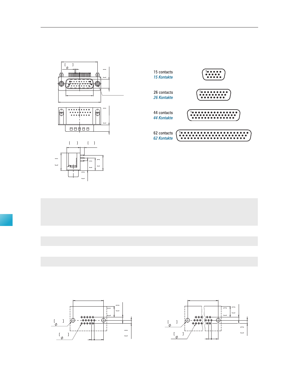
Pin: Right Angled PCB Termination
Dimensions
Abmessungen
PCB Hole Pattern (Mounting Side)
Leiterplattenlochbild (Bestückungsseite)
Stift: Abgewinkelter
Leiterplattenanschluss
Pin Connector, Front View
Stiftsteckverbinder, Frontansicht
100 I connecting is our business
High Density Connectors
High Density Steckverbinder
Product Description
Produktbeschreibung
4-40 UNC-2B; M3
C
B
0.028
0.7
8.
2
0.
323
A
5.
9
±
0
.0
2
0.
232
±
0
.0
0
0
8
11.
44
0.
45
8.
9
0.
35
13.
98
0.
55
0.492
12.5
3.8
0.15
16
0.
63
4-40 UNC-B or M clinch nut on connector flange available.
Mit 4-40 UNC-2B bzw. M3 Gewindeniet im Steckerflansch lieferbar.
Stamped contacts
Gestanzte Kontakte
1
J
C
0.
35
8.
9
0.
1
2.
54
3.18
0.125
H
2.
54
0.
1
1.2
0.047
Hole Pattern 1 Contacts
Lochbild 15-polig
1
0.047
J
C
1.2
3.18
0.125
H
2.
54
0.
1
2.
54
0.
1
8.
9
0.
35
Hole Pattern , 44 and Contacts
Lochbild 26-, 44- und 62-polig
Shell Size
Number of Contacts
A
B
C
H
J
Gehäusegröße
Polzahl
Grounding Brackets
with Snap-in
Grounding Brackets
with Snap-in
Grounding Brackets
without Snap-in
Snap-in Massewinkel Snap-in Massewinkel
Massewinkel ohne
Snap-in
±0,4
+0,2
±0,15
4-40 UNC-2B
M3
4-40 UNC-2B
(±0.016)
(+0.008)
(±0.006)
30,8
16,9
25,0
7,10
2,29
(1.213)
(0.665)
(0.984)
(0.280)
(0.090)
39,1
25,2
33,3
6,80
2,29
(1.539)
(0.992)
(1.311)
(0.268)
(0.090)
53,0
38,9
47,0
7,00
2,29
(2.087)
(1.531)
(1.852)
(0.276)
(0.090)
69,3
55,3
63,5
7,00
2,42
(2.728)
(2.177)
(2.500)
(0.276)
(0.095)
Dimensions in mm (inch) -
Abmessungen in mm (inch)
CT15-26P5-L228
CT15-26P5-L229
CT15-26P5-L222
2
26
CT25-44P5-L228
CT25-44P5-L229
CT25-44P5-L222
3
CT37-62P5-L222
Order Number
Bestellnummer
CT09-15P5-L222
CT09-15P5-L229
CT37-62P5-L228
CT37-62P5-L229
4
1
15
44
62
CT09-15P5-L228