Pin: straight pcb termination, Stift: gerader leiterplattenanschluss – FMK High Density D-Sub User Manual
Page 4
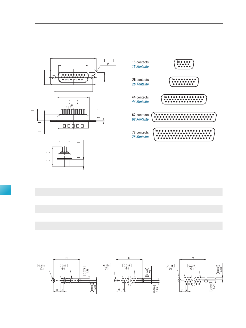
Pin: Straight PCB Termination
Dimensions
Abmessungen
PCB Hole Pattern (Mounting Side)
Leiterplattenlochbild (Bestückungsseite)
Stift: Gerader Leiterplattenanschluss
Pin Connector, Front View
Stiftsteckverbinder, Frontansicht
98 I connecting is our business
High Density Connectors
High Density Steckverbinder
Product Description
Produktbeschreibung
D
B
A
E
C
3
0.118
0.024
0.6
0.
9
0.
035
G
5.
5
0.
217
9.
5
0.
374
F
5.
9
±
0
.2
0.
232
±
0
.0
0
8
16.
3
0.
642
Stamped contacts
Gestanzte Kontakte
Hole Pattern 1 Contacts
Lochbild 15-polig
Hole Pattern , 44 and Contacts
Lochbild 26-, 44- und 62-polig
Hole Pattern 78 Contacts
Lochbild 78-polig
Order Number
Shell Size
Number of Contacts
A
B
C
D
E
F
G
H
J
Bestellnummer
Gehäusegröße
Polzahl
±0,4
+0,2
±0,15
+0,2
±0,4
±0,3
±0,3
(±0.016)
(+0.008)
(±0.006)
(+0.008)
(±0.016)
(±0.012)
(±0.012)
30,8
16,9
25,0
8,2
12,5
10,8
19,3
7,10
2,29
(1.213)
(0.665)
(0.984)
(0.323)
(0.492)
(0.425)
(0.760)
(0.280)
(0.090)
39,1
25,2
33,3
8,2
12,5
10,8
27,5
6,80
2,29
(1.539)
(0.992)
(1.311)
(0.323)
(0.492)
(0.425)
(1.083)
(0.268)
(0.090)
53,0
38,9
47,0
8,2
12,5
10,8
41,3
7,00
2,29
(2.087)
(1.531)
(1.852)
(0.323)
(0.492)
(0.425)
(1.626)
(0.276)
(0.090)
69,3
55,3
63,5
8,2
12,5
10,8
57,7
7,00
2,42
(2.728)
(2.177)
(2.500)
(0.323)
(0.492)
(0.425)
(2.272)
(0.276)
(0.095)
66,9
52,8
61,1
11,0
15,4
13,7
55,3
7,60
2,42
(2.634)
(2.079)
(2.406)
(0.433)
(0.606)
(0.539)
(2.177)
(0.299)
(0.095)
Dimensions in mm (inch) -
Abmessungen in mm (inch)
CT50-78P1
15
26
44
62
78
CT09-15P1
CT15-26P1
CT25-44P1
CT37-62P1
5
1
2
3
4