Bunn VPS User Manual
Page 10
Page 10
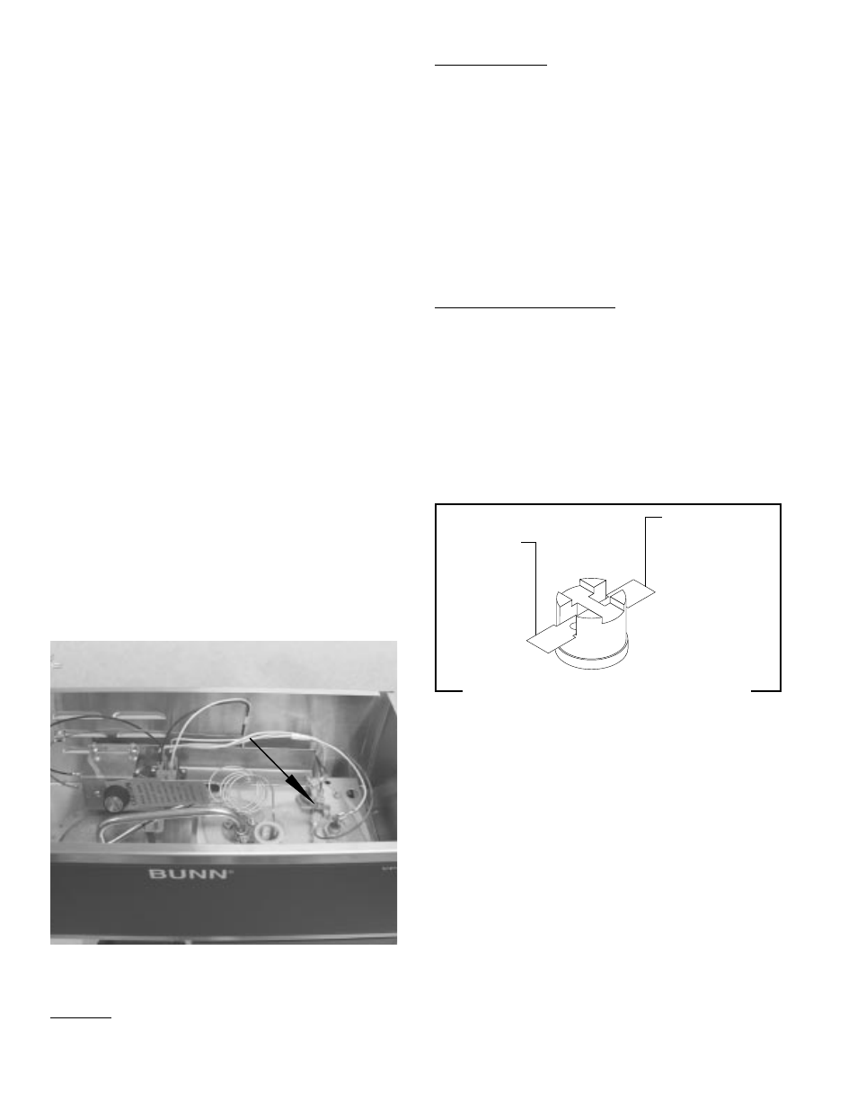
FIG. 6 LIMIT THERMOSTAT TERMINALS
SERVICE (cont.)
CONTROL THERMOSTAT (cont.)
LIMIT THERMOSTAT - VPR, VPS
Location:
The limit thermostat is located inside the hood on
the right side of the tank lid.
P2414
FIG. 5 LIMIT THERMOSTAT
P1800
BLK to Tank
Heater
BLU/BLK to Control
Thermostat
10053 073001
2.
Remove the thermostat capillary bulb by firmly
pulling-up on the capillary at the tank lid. This will
disengage the grommet from the tank lid.
3.
Remove the two #8-32 screws securing the con-
trol thermostat to the mounting bracket inside
the hood.
4.
Slide the grommet to the line 4.5" above the bulb
on the new capillary tube.
5.
Insert the capillary bulb through the hole in the
tank lid and press the grommet firmly and evenly
so that the groove in the grommet fits into the
tank lid.
6.
Carefully bend the capillary tube so that the tube
and bulb inside the tank are in the vertical posi-
tion.
NOTE - The capillary tube must be clear of any electri-
cal termination and not kinked.
7.
Using two #8-32 screws secure the control ther-
mostat to the mounting bracket inside the hood.
8.
Refer to Fig. 4 when reconnecting the wires.
9.
Adjust the control thermostat as required
Test Procedures:
1.
Disconnect the brewer from the power source.
2.
Disconnect the blue/black and black wires from
the limit thermostat.
3.
Check for continuity across the limit thermostat
terminals with an ohmmeter.
If continuity is present as described, the limit thermo-
stat is operating properly.
If continuity is not present as described, replace the
limit thermostat.
Removal and Replacement:
1.
Remove all wires from limit thermostat termi-
nals.
2.
Carefully slide the limit thermostat out from
under the retaining clip and remove limit thermo-
stat.
3.
Carefully slide the new limit thermostat into the
retaining clip.
4.
Refer to Fig. 6 when reconnecting the wires.