Clarus Environmental Turbine Effluent Pumps User Manual
Page 5
5
© Copyright 2014. All rights reserved.
SK2222
Major Components
1. Submersible Turbine Effluent Pump - A submersible turbine
effluent pump is a multistage centrifugal design pump. Each stage
consists of an impeller and diffuser. Water pressure increases in
equal amounts as it passes from stage to stage. The more stages,
the higher the pressure the pump will develop.
To correctly select a pump for a specific application, the following
information must be known:
• The amount of discharge required in GPM or LPM
• The total dynamic head required in feet or meters
Use this information along with the performance data found on the
previous page to make your selection.
2. Controls - Submersible turbine effluent pumps require the use of
an above ground control panel or junction box with a pump control
switch for proper operation. Operation of these pumps without a
control panel or junction box with a pump control switch can result in
failure of the pump and void the warranty. At least three elevations
must be determined to control a pump within a given tank or basin:
pump on level, pump off level and high water alarm level.
3. Piping - The submersible turbine effluent pump can be installed with
schedule 40 PVC pipe. The pipe size should be 1¼” diameter for
the 11 GPM to 27 GPM pump series and 2” diameter for the 35-85
GPM pump series.
General piping from the pump to a splitter, distribution box, drain
field etc., should be the same diameter as stated above. For long
pipe runs consult friction loss tables for correct pipe sizing.
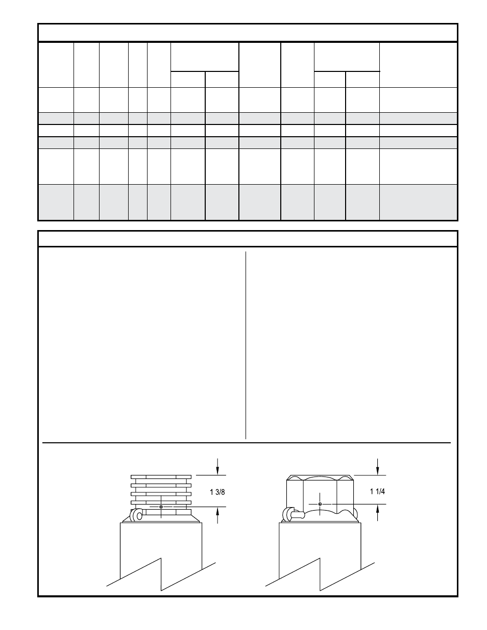
4. Check Valve - A check valve is required in all duplex systems. It is
also required when a large amount of effluent can backflush into the
system causing rapid cycling of the pump.
A 1/8” weep hole must be drilled in the side of the discharge
head when using a check valve (see drawing below for drill
location).
Electrical Data for Clarus Environmental Turbine Effluent Pumps
locked
fuse/Circuit
winding
Maximum
Rotor
kVA breaker Amps
Resistance
hP
Volts Phase hz S.f. Amps watts
Amps
Code Std.
Delay
line to line
1/2
115
1
60 1.6
12
970
64.4
R
30
15
1.0 - 1.3
1/2
230
1
60 1.6
6
970
32.2
R
15
8
4.2 - 5.2
3/4
230
1
60 1.5
8
1325
40.7
N
20
10
3.0 - 3.6
1
230
1
60 1.4
10.4
1600
48.7
N
25
11
2.2 - 2.7
1 1/2
230
1
60 1.3
13.1
2250
56.8
L
35
15
1.5 - 1.9
2
230
1
60 1.25 Y 13.2
2650
51.0
G
30
15
1.6 - 2.3 M
B 11.9
5.2 - 7.15 S
R 2.6
3
230
1
60 1.15 Y 14.0
3650
82.0
G
45
20
.9 - 1.5 M
B 14.5
3.0 - 4.9 S
R 4.5
35-85 GPM MODELS
11-27 GPM MODELS