System installation instructions, continued, Figure 3 - tethered pump switch, Figure 4 - j-box wiring diagram – Clarus Environmental Centrifugal STEP Systems User Manual
Page 3
3
© Copyright 2014. All rights reserved.
7. Bring piping from the lateral field to the outside of the riser on the
septic tank. Note: If installing a system using a control panel follow
the instructions included with the panel and skip steps 11-12 and 15.
8. Disconnect Clarus Environmental flexible pipe assembly at union
on ball valve. Install pipe seal through the riser wall (2” hole saw
required) to prevent ground water intrusion. Install flexible pipe
through pipe seal with union ball valve on inside of riser as shown
in Figure 1A. Solvent weld flexible pipe to lateral field piping using
PVC pipe cement.
9. Connect other part of 1 ¼” discharge pipe assembly to pump outlet
with pump setup outside the pump tank.
10. Tie off power cord by strapping to the discharge pipe. Make certain
the cord cannot become entangled or obstruct the movement
of the floats.
11. Install wire from power source and the alarm. See Fig. 1A or 1B. If
a junction box is being used, Fig. 1A, install inside the septic tank
riser. If a Qwik Box System is being used, Fig. 1B, install outside of
septic tank riser as shown in Fig. 1B or inside of septic tank riser.
Note: Some codes require the junction box to be outside the riser.
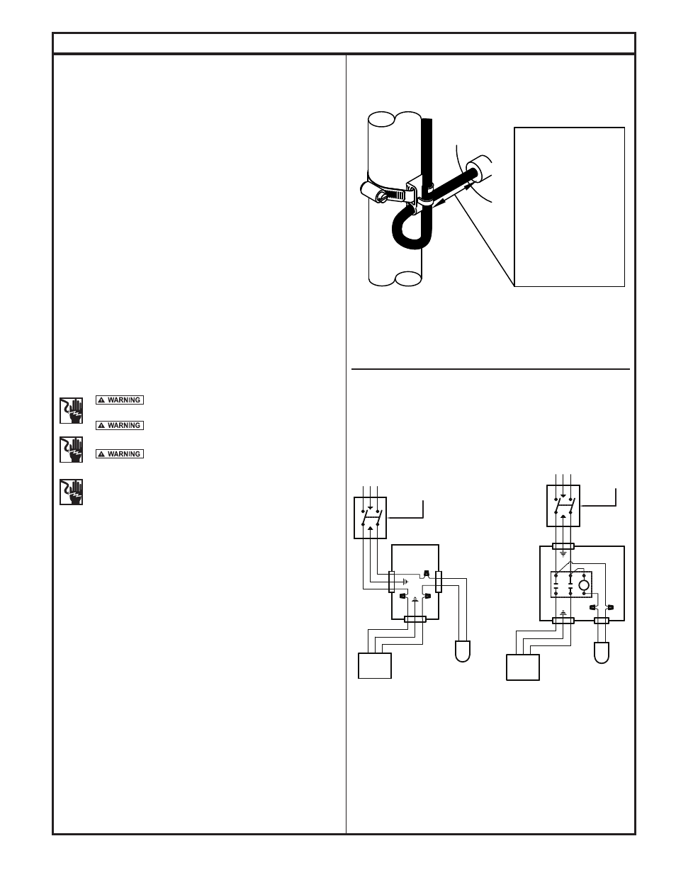
12. Install pump switch on discharge pipe using the included band clamp.
Place the band clamp as low on the discharge pipe as possible.
Tether the pump switch so that 3.5" of cord exists between the float
and the clamp. This will yield a 7" drawdown cycle. Additional
tethers can be used if state, local and regional codes permit.
System Installation Instructions, continued
Figure 3 - Tethered Pump Switch
SK1301
Note: Some codes require the junction box to be outside the riser.
Figure 4 - J-Box Wiring Diagram
“Risk of electrical shock” Do not remove power
supply cord and strain relief or connect conduit directly to the pump.
Installation and checking of electrical circuits and
hardware should be performed by a qualified licensed electrician.
For your protection make certain the pump
ground wire is properly connected to the ground wire with the
incoming power line. Test for ground at the junction box using
an Underwriters Laboratory listed circuit analyzer which will indicate
if the power, neutral and ground wires are correctly connected. If in
doubt, call a qualified licensed electrician.
13. Measure length of hanger pipes by measuring inside the riser. Cut and
install hanger pipes in filter tank and lower the assembly into the septic
tank opening. Tie off power cords by strapping to discharge pipe. Make
certain cords cannot become entangled or obstruct the movement of the
floats. See Fig. 1. Lower pump with discharge pipe and float assemblies
into filter tank.
14. Adjust piping using threaded elbows and flexible piping provided to achieve
proper fit. Connect union on ball valve.
15. Install the alarm inside the house or in a weather protected location per
installation instructions with alarm kit, making sure the alarm is plugged into
a different circuit than the pump circuit. Complete the wiring connections. If
a junction box is being used, Fig. 1A, wire per diagram in Fig. 4. If a Qwik
Box outside connection is being used, wire according to the installation
instruction provided with the Qwik Box unit. All wiring, from the power
source to the pump, must conform to the National Electrical Code. Be
sure to leave a sufficient amount of cord so the filter can be serviced
without disconnecting the cordage from the junction box or Qwik box.
See Maintenance section on back page.
16. Fill the septic tank with water and check the alarm level before placing
the system into service. See operation and start-up areas of this manual.
SWITCH
SK306
3.5 INCH
TETHER LENGTH
FOR DOUBLE
FLOAT
3.5 INCH
MINIMUM
TETHER LENGTH
FOR PUMP
SWITCH
WHITE
BLACK
WHITE
GREEN
BLACK
BLACK
GREEN
WHITE
BLACK
WHITE
R
L1
L2
L2
L1
PUMP
DISCONNECT
SWITCH
WATERTIGHT
JUNCTION BOX
VARIABLE
LEVEL
PUMP SWITCH
PUMP
CONTROL SWITCH
VARIABLE
LEVEL
DISCONNECT
SWITCH