chiliGREEN K8NHA Grand User Manual
Page 15
K
K
8
8
N
N
H
H
A
A
G
G
r
r
a
a
n
n
d
d
15
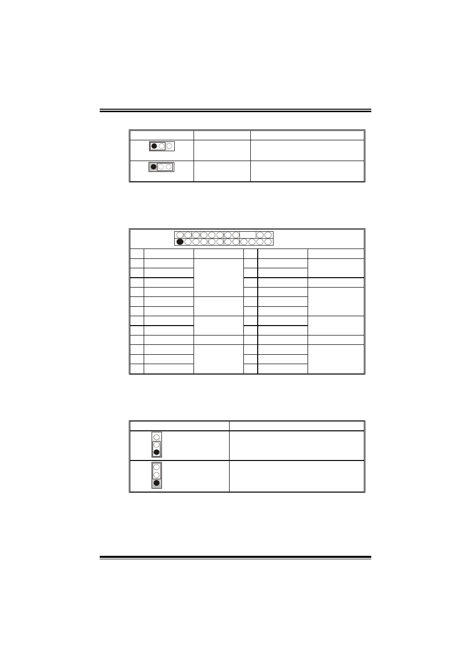
Power Source for 1394: J1394V1
J1394V1 Assignment
Description
1
3
Pin 1-2 close
+3.3V SB
+3.3V SB for 1394 chipset.
1
3
Pin 2-3 close
+3.3V
+3.3V for 1394 chipset.
(Default)
Front Panel Connector: JPANEL1
This 24-pin connector includes Power-on, Reset, HDD LED, Power
LED, Sleep button, speaker and IrDA Connection. It allows user to
connect the PC case’s front panel switch functions.
2
24
1
23
JPANEL1
Pin Assignment Function Pin Assignment
Function
1 +5V 2 Sleep
control
3 N/A 4 Ground
Sleep button
5 N/A 6 N/A
N/A
7 Speaker
Speaker
Connector
8 Power LED (+)
9 HDD LED (+)
10 Power LED (+)
11 HEE LED (-)
Hard drive
LED
12 Power LED (-)
Power LED
13 Ground 14 Power
button
15 Reset control
Reset button
16 Ground
Power-on button
17 N/A
18 Key
19 N/A 20 Key
21 +5V 22 Ground
23 IRTX
IrDA
Connector
24 IRRX
IrDA Connector
Close CMOS Jumper: JCMOS1
By placing the jumper on pin2-3, it allows user to restore the BIOS
safe setting and the CMOS data, please carefully follow the
procedures to avoid damaging the motherboard.
JCMOS1 Assignment
1
3
Pin 1-2 close
Normal Operation (Default).
1
3
Pin 2-3 close
Clear CMOS data.
※
※
※
※ Clear CMOS Procedures:
1. Remove AC power line.
2. Set the jumper to “Pin 2-3 close”.
3. Wait for five seconds.
4. Set the jumper to “Pin 1-2 close”.