3 fan monitoring – chiliGREEN D915PGNL User Manual
Page 37
Product Description
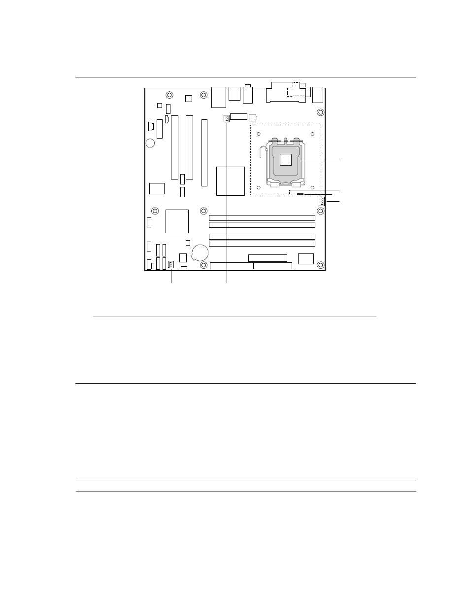
Figure 14 shows the location of the sensors and fan connectors for the D915PSY board.
OM17057
A
B
E
F
D
C
1
4
1
3
1
3
Item Description
A
Thermal diode, located on processor die
B
Remote ambient temperature sensor
C
Ambient temperature sensor, internal to hardware monitoring and fan control ASIC
D
Processor fan
E
Rear chassis fan
F
Front chassis fan
Figure 14. Thermal Monitoring for D915PSY Board
1.12.3 Fan
Monitoring
Fan monitoring can be implemented using Intel
®
Desktop Utilities, LANDesk* software, or third-
party software. The level of monitoring and control is dependent on the hardware monitoring ASIC
used with the Desktop Board.
For information about
Refer to
The functions of the fan connectors
Section 1.13.2.2, page 42
37