4 thermal monitoring, Thermal monitoring, 8-channel (7.1) audio subsystem block diagram – chiliGREEN D945GBO User Manual
Page 36
Intel Desktop Board D945GBO Technical Product Specification
36
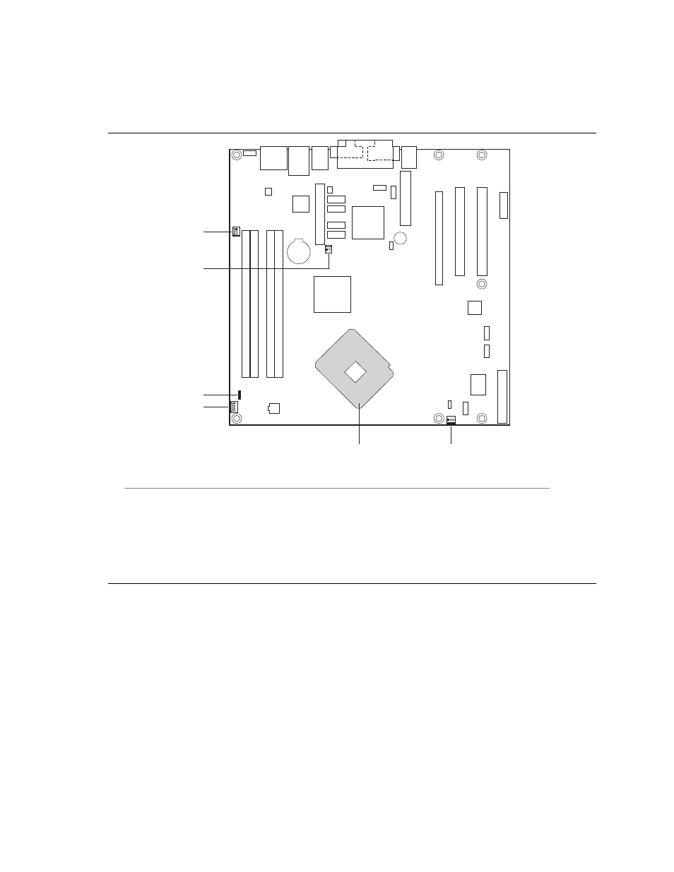
1.12.4 Thermal
Monitoring
Figure 12 shows the location of the sensors and fan connectors.
OM17936
E
D
C
A
F
B
3
1
1
2
1
4
1 3
Item Description
A
Remote ambient temperature sensor
B
Thermal diode, located on processor die
C
Ambient temperature sensor, internal to hardware monitoring and fan control ASIC
D
Processor fan
E
Rear chassis fan
F
Front chassis fan
Figure 12. Thermal Sensors and Fan Connectors
See also other documents in the category chiliGREEN Computers:
- IPMTB-GS (30 pages)
- IPMIP GS (7 pages)
- IPI43 (6 pages)
- IPAEL-GS (6 pages)
- RC410M -A82C (40 pages)
- D946GZTS (76 pages)
- D945GBZ (92 pages)
- D915PGNL (107 pages)
- D915GAGL (106 pages)
- GA-A75M-S2V (44 pages)
- GA-A75M-UD2H (96 pages)
- GA-7VT600-p-l (112 pages)
- GA-8I955X (88 pages)
- GA-8I945P Duo Graphic-R (88 pages)
- GA-8IPE1000-MK (96 pages)
- M7VIT-Grand (54 pages)
- M7VIT (38 pages)
- M7VIQ (27 pages)
- M7NCD-Ultra (41 pages)
- M7NCD-Pro (41 pages)
- K8VHA Pro (31 pages)
- K8NHA-M Grand (32 pages)
- K8NHA-M (28 pages)
- K8NHA Grand (32 pages)
- P4VTGM (56 pages)
- P4VTC (28 pages)
- P4VTB (40 pages)
- P4VMA-M (32 pages)
- P4TSP-D2 (52 pages)
- P4TSE (40 pages)
- P4TPT (34 pages)
- Card Reader UCR-61S2B Q&A (8 pages)
- BT100 (37 pages)
- P5VDC-MX (94 pages)
- P5RD2-TVM (90 pages)
- P5G41T-M LX2 (722 pages)