4 block diagram, Block diagram, Figures – chiliGREEN D945GBO User Manual
Page 14
Intel Desktop Board D945GBO Technical Product Specification
14
1.2.4 Block
Diagram
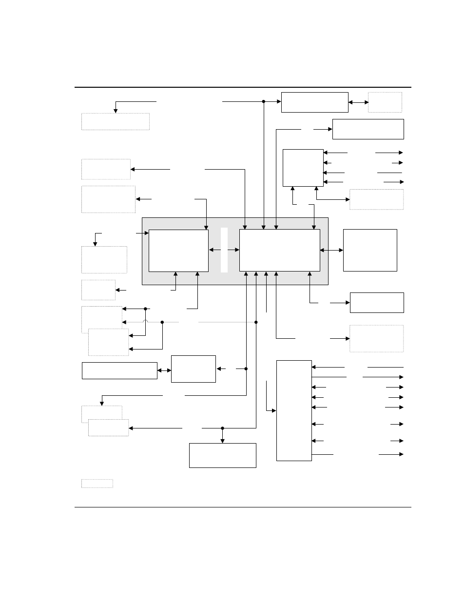
Figure 2 is a block diagram of the major functional areas.
Intel 945G Chipset
Intel 82801GH
I/O Controller Hub
(ICH7DH)
Intel 82945G
Graphics and
Memory Controller
Hub (GMCH)
Serial Peripheral
Interface (SPI)
Flash Device
System Bus
(1066/800 MHz)
LGA775
Processor Socket
Parallel ATA
IDE Connector
Diskette Drive
Connector
Legacy
I/O
Controller
PS/2 Keyboard
PS/2 Mouse
Parallel Port (Optional)
Serial Port
Parallel ATA
IDE Interface
LPC
Bus
Hardware Monitoring
and Fan Control ASIC
OM18266
Audio
Codec
PCI Express
x16 Interface
PCI Express
x16
Connector
= connector or socket
PCI Bus
SMBus
H
igh
Def
in
it
ion Au
di
o
L
ink
USB
Dual-Channel
Memory Bus
SMBus
PCI Slot 1
PCI Slot 2
Serial ATA IDE
Connectors (4)
Serial ATA
IDE Interface
VGA
Port
Display Interface
Channel A
DIMMs (2)
Channel B
DIMMs (2)
Back Panel/Front Panel
USB Ports
D
M
I I
n
tercon
nect
TPM Component
(Optional)
LPC
Bus
PCI Express x1 Slot 1
PCI Express x1 Interface
LAN
Connector
Gigabit Ethernet
Controller
Line Out/Retasking Jack
Mic In
Line In/Retasking Jack
Mic In/Retasking Jack
S/PDIF (optional)
Surround L-R/
Retasking Jack (optional)
Center and LFE/
Retasking Jack (optional)
Line Out
PCI
Bus
IEEE-1394a Connectors
IEEE-1394a
Controller
Figure 2. Block Diagram